


Introduction
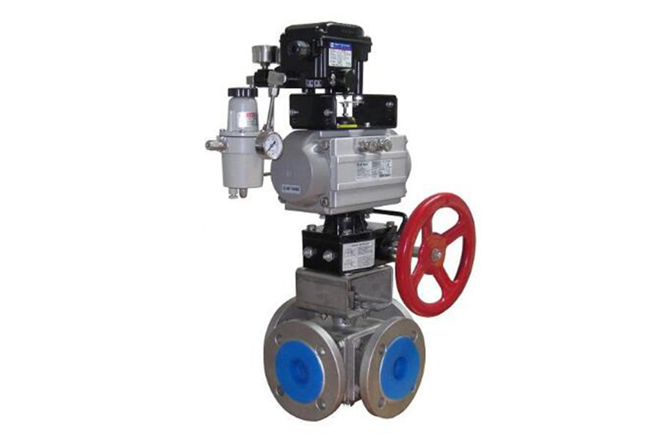
The packing selection for Q646F pneumatic four-way ball valve is braided, flexible graphite sealing ring or PTFE sealing ring, which ensures reliable sealing of the valve stem under certain lubrication conditions. As needed, ball valves can be designed with anti-static structures, with conductive springs installed between the ball and valve stem, as well as between the valve stem and valve body, to prevent static electricity from igniting flammable substances and ensure system safety. There are various forms of sealing pairs. According to different working conditions, structures such as soft seals, hard seals, and fire-resistant valve seats can be selected; Below DN150 is in the form of a floating ball, and below DN200 is in the form of a fixed ball. An auxiliary sealing structure can be installed at the valve seat of the ball valve, and a grease injection valve can be added to the valve seat and stem for temporary sealing in emergency situations. The stem can also be extended as needed to be suitable for underground installation.
Technical Parameter
Main Part Materials and Performance of Q46F Four-way Ball Valve
| Valve Body | Valve Stem | Valve Ball | Sealing Surface | Gasket | Packing | Operating Temperature | Suitable Medium |
|---|---|---|---|---|---|---|---|
| WCB | 1Cr13 | 1Cr13 |
1Cr13 |
Flexible Graphite |
Flexible Graphite |
-29 - 425℃ | Water, Steam, Oil Products |
| WC6 | 15CrMo | 15CrMo | -29 - 425℃ | ||||
| WC9 | 25Cr2MoV | 25Cr2MoV | |||||
| LCB | 304 | 304 | -46 - 354℃ | ||||
| CF8 | 304 | 304 | -196 - 600℃ | Some Acids and Alkalis | |||
| CF3 | 304L | 304L | |||||
| CF8M | 316 | 316 | |||||
| CF3M | 316L | 316L |
Main Connection Dimensions and Weight of Q46F Four-way Ball Valve: PN1.6MPa
| Nominal Diameter DN | 150 | 200×150 | 200 | 250×200 | 250 | 300×250 | 300 | 350×300 | 350 | 400×350 | 400 | 450×400 | 450 | 500×450 | 500 | 600×500 | 600 | |
|---|---|---|---|---|---|---|---|---|---|---|---|---|---|---|---|---|---|---|
| Ball Hole d1 | 150 | 150 | 200 | 200 | 250 | 250 | 300 | 300 | 350 | 350 | 400 | 400 | 450 | 450 | 500 | 500 | 600 | |
| L | 570 | 570 | 670 | 670 | 760 | 760 | 850 | 850 | 980 | 980 | 1080 | 1080 | 1220 | 1220 | 1360 | 1360 | 1750 | |
| H | 219 | 219 | 273 | 273 | 360 | 360 | 395 | 395 | 430 | 430 | 470 | 470 | 550 | 550 | 580 | 580 | 700 | |
| Manual | H1 | 330 | 330 | 398 | 398 | 495 | 495 | 580 | 580 | 625 | 625 | 670 | 670 | 698 | 698 | 840 | 840 | 1050 |
| E | - | - | 116 | 116 | 116 | 116 | 171 | 171 | 171 | 171 | 257 | 257 | 257 | 257 | 257 | 257 | 150 | |
| F | - | - | 350 | 350 | 350 | 350 | 400 | 400 | 420 | 420 | 400 | 400 | 420 | 420 | 400 | 400 | 410 | |
| W | 1050 | 1050 | 600 | 600 | 600 | 600 | 800 | 800 | 800 | 800 | 800 | 800 | 800 | 800 | 800 | 800 | 800 | |
| Electric | H2 | 554 | 554 | 600 | 600 | 652 | 652 | 760 | 760 | 770 | 770 | 830 | 830 | - | - | 940 | 940 | 1020 |
| L1 | 235 | 235 | 235 | 235 | 235 | 235 | 259 | 259 | 400 | 400 | 400 | 400 | - | - | 410 | 410 | 410 | |
| Pneumatic | H3 | 666 | 666 | 736 | 736 | 926 | 926 | 1059 | 1059 | 1127 | 1127 | 1393 | 1393 | 1468 | 1468 | 1538 | 1538 | 1370 |
| L2 | 776 | 776 | 736 | 736 | 776 | 776 | 1060 | 1060 | 1060 | 1060 | 1360 | 1360 | 1360 | 1360 | 1360 | 1360 | 2840 | |
Performance Specifications
| Nominal Pressure PN | Maximum Working Pressure at Room Temperature | Shell Test Pressure | Gas Seal Test Pressure | High-pressure Seal Test Pressure |
|---|---|---|---|---|
| 1.6 | 1.6 | 2.4 | 0.6 | 1.76 |
| 2.5 | 2.5 | 3.8 | 0.6 | 2.75 |
| 4.0 | 4.0 | 6.0 | 0.6 | 4.4 |
| Class150 | 2.0 | 3.0 | 0.6 | 2.2 |
Test Pressure Unit: Mpa Application Range and Main Part Materials
| Valve Body/Valve Cover | GB | WCB | ZG1Cr18Ni9Ti | ZG0Cr18Ni12Mo2Ti | |||
|---|---|---|---|---|---|---|---|
| ASTM | WCB | CF8 | CF8M | ||||
| Ball | GB | 2Cr13 | 1Cr18Ni9Ti | 0Cr18Ni12Mo2Ti | |||
| ASTM | 420 | 304 | 316 | ||||
| Valve Stem | GB | 2Cr13 | 1Cr18Ni9Ti | 0Cr18Ni12Mo2Ti | |||
| ASTM | 420 | 304 | 316 | ||||
| Valve Seat Sealing Surface | GB | Polytetrafluoroethylene | Para-polyphenylene | Polytetrafluoroethylene | Para-polyphenylene | Polytetrafluoroethylene | Para-polyphenylene |
| ASTM | |||||||
| Packing | GB | Flexible Graphite | Flexible Graphite | Flexible Graphite | |||
| ASTM | |||||||
| Bolt | GB | 35 | 0Cr18Ni9 | 0Cr18Ni9 | |||
| ASTM | A193B7 | A320-B8 | A320-B8 | ||||
| Nut | GB | 45 | 0Cr18Ni9 | 0Cr18Ni9 | |||
| ASTM | A1942H | A194-8 | A194-8 | ||||
Main Connection Dimensions
| Nominal Pressure PN | Nominal Diameter DN | Dimensions (mm) | |||||||||
|---|---|---|---|---|---|---|---|---|---|---|---|
| L | L0 | D | K | d | Y | b | z-do | Hw | Hd | ||
| 1.6MPa | 50 | 260 | 130 | 165 | 125 | 100 |
|
16 | 4-ф18 | 205 | 265 |
| 65 | 320 | 160 | 185 | 145 | 120 |
|
18 | 4-ф18 | 245 | 295 | |
| 80 | 320 | 160 | 200 | 160 | 135 |
|
20 | 8-ф18 | 305 | 345 | |
| 100 | 370 | 185 | 220 | 180 | 155 |
|
20 | 8-ф18 | 340 | 420 | |
| 125 | 510 | 255 | 250 | 210 | 185 |
|
22 | 8-ф18 | 425 | 465 | |
| 150 | 510 | 255 | 285 | 240 | 210 |
|
24 | 8-ф23 | 450 | 505 | |
| 200 | 580 | 290 | 340 | 295 | 265 |
|
26 | 12-ф23 | 480 | 525 | |
| 250 | 670 | 335 | 405 | 355 | 320 |
|
30 | 12-ф25 | 530 | 565 | |
| 300 | 760 | 380 | 460 | 410 | 375 |
|
30 | 12-ф25 | 585 | 630 | |
| 350 | 850 | 425 | 520 | 470 | 435 |
|
34 | 16-ф25 | 625 | 675 | |
| 400 | 980 | 490 | 580 | 525 | 485 |
|
36 | 16-ф30 | 670 | 710 | |
| 450 | 1080 | 540 | 640 | 585 | 545 |
|
40 | 20-ф30 | 705 | 770 | |
| 500 | 1220 | 610 | 715 | 650 | 608 |
|
44 | 20-ф34 | 765 | 825 | |
| 600 | 1360 | 680 | 840 | 770 | 718 |
|
48 | 20-ф41 | 840 | 945 | |
| 700 | 1750 | 875 | 910 | 840 | 788 |
|
50 | 24-ф41 | 1050 | 1110 | |
| 800 | 1850 | 925 | 1025 | 950 | 898 |
|
52 | 24-ф41 | 1125 | 1220 | |
| 900 | 2050 | 1025 | 1125 | 1050 | 998 |
|
54 | 28-ф41 | 1260 | 1315 | |
| 1000 | 2150 | 1075 | 1255 | 1170 | 1110 |
|
56 | 28-ф48 | 1325 | 1385 | |
| 1200 | 2450 | 1225 | 1485 | 1390 | 1325 |
|
58 | 32-ф54 | 1395 | 1450 | |
| 2.5MPa | 50 | 260 | 130 | 165 | 125 | 100 |
|
20 | 4-ф18 | 205 | 265 |
| 65 | 320 | 160 | 185 | 145 | 120 |
|
22 | 8-ф18 | 245 | 295 | |
| 80 | 320 | 160 | 200 | 160 | 135 |
|
22 | 8-ф18 | 305 | 345 | |
| 100 | 370 | 185 | 230 | 190 | 160 |
|
24 | 8-ф23 | 340 | 420 | |
| 125 | 510 | 255 | 270 | 220 | 188 |
|
28 | 8-ф25 | 405 | 465 | |
| 150 | 510 | 255 | 300 | 250 | 218 |
|
30 | 8-ф25 | 450 | 505 | |
| 200 | 580 | 290 | 360 | 310 | 278 |
|
34 | 12-ф25 | 480 | 525 | |
| 250 | 670 | 335 | 425 | 370 | 332 |
|
36 | 12-ф30 | 530 | 565 | |
| 300 | 760 | 380 | 485 | 430 | 390 |
|
40 | 16-ф30 | 585 | 630 | |
| 350 | 850 | 425 | 555 | 490 | 448 |
|
44 | 16-ф34 | 625 | 675 | |
| 400 | 980 | 490 | 620 | 550 | 505 |
|
48 | 16-ф34 | 670 | 710 | |
| 450 | 1080 | 540 | 670 | 600 | 555 |
|
50 | 20-ф34 | 705 | 770 | |
| 500 | 1220 | 610 | 730 | 660 | 610 |
|
52 | 20-ф41 | 765 | 825 | |
| 600 | 1360 | 680 | 845 | 770 | 718 |
|
56 | 20-041 | 840 | 945 | |
| 700 | 1750 | 875 | 960 | 875 | 815 |
|
60 | 24-ф48 | 1050 | 1110 | |
| 800 | 1850 | 925 | 1085 | 990 | 930 |
|
64 | 24-ф48 | 1125 | 1220 | |
Valve Installation & Maintenance
Valve Installation:
(1) Before installation, check that the product model, tag number, and specifications match the requirements. Inspect the entire valve for missing or loose parts.
(2) Prior to installation, clean the pipeline. Ensure there is sufficient straight pipe section at the valve inlet and install a filter. When connecting the valve body to the pipeline flanges, ensure coaxiality.
(3) Thoroughly clean the pipeline before installing the valve.
(4) The installation site should ensure the safety of personnel and equipment, facilitating operation, disassembly, and maintenance.
(5) The valve should be installed vertically upright on horizontal pipelines. If necessary, it can be installed at an angle, but horizontal installation should be avoided. For occasions with heavy valve weight or vibration, use a support frame.
(6) The medium flow direction must align with the arrow on the valve body. The air supply should be dry and oil-free. The valve should be used in environments with temperatures ranging from -20℃ to 55℃.
Valve Maintenance:
(1) Cleaning the Valve: For general media, cleaning with water is sufficient. For media harmful to health, first understand their properties and then select an appropriate cleaning method.
(2) Disassembly: Remove rust from exposed rusted parts first. Before derusting, protect the machined surfaces of precision parts such as the valve seat, valve plug, valve stem, and push rod. Use special tools when disassembling the valve seat.
(3) Valve Seat: Minor rust or wear on the sealing surface can be repaired by machining. If damage is severe, replace the seat. However, both repaired and replaced hard sealing surfaces must be lapped.
(4) Valve Stem: If the surface is damaged, it must be replaced.
(5) Damage to Push Rod, Guide, and Sealing Surfaces: Reverse-acting actuators must be replaced; direct-acting actuators can be reused after proper repair.
(6) Compression Spring: If there are cracks or other defects affecting strength, replace it immediately.
(7) Wear Parts: Packing, gaskets, and O-rings must be replaced entirely during each maintenance. Check the valve plug and diaphragm for cracks, aging, or corrosion that may cause future failures. Decide whether to replace them based on inspection results, but the diaphragm service life should not exceed 2-3 years.
(8) When reassembling the valve, ensure alignment. Tighten bolts diagonally and lubricate sliding parts. After reassembly, debug the valve according to the factory test items and methods. During this period, accurately adjust the packing compression force and the valve plug closing position.
Ordering Instructions
When placing an order, please fill in the Specification Sheet or specify the following information:
-
If the model has not been selected before ordering, please provide us with the operating parameters:
(1) Nominal diameter DN (mm);
(2) Nominal pressure (MPa or bar);
(3) Fluid properties (including medium temperature, viscosity, or acidity/alkalinity);
(4) Pressure before and after the valve (pressure differential);
(5) Requirements for flow characteristics;
(6) Materials of valve body and valve core;
(7) Connection type;
(8) Driving method (provide air supply pressure, driving voltage);
(9) Supporting accessories (for pneumatic valves, it is recommended that users install an air filter triplet and a 2-position 5-way solenoid valve);
(10) On-site working conditions. -
If the product model of our company has been selected by the design unit, please order directly from our production department according to the model;
-
When the application occasion is very important or the pipeline is relatively complex, please provide the design drawings and detailed parameters as much as possible, and our experts will review and check them for you.


