


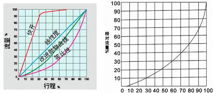
2. Excellent regulating characteristics: Pneumatic V-ball valves have an approximately equal percentage of inherent flow characteristics and an adjustable ratio of up to 300:1. Therefore, the V-shaped regulating ball valve can provide precise control over a wide range of changes.
3. Maximum flow volume: Due to its streamlined shape and full right angle rotation control, the maximum volume is particularly high, the flow capacity is particularly large, and the flow resistance is small. Therefore, smaller and more economical valve sizes can be used.
4. The pneumatic V-ball valve adopts a double bearing structure, with high mechanical stability and low starting torque, ensuring excellent sensitivity and sensing speed of the valve.
5. Maximum reliability (safety): The valve body is a solid and durable structure, which is not affected by pipeline pressure during operation and can prevent valve body leakage.
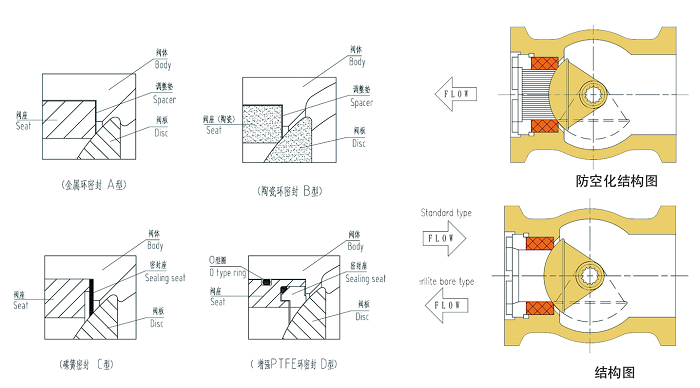
6. Superior sealing performance of metal valve seat: The pneumatic V-ball valve adopts an elastic movable metal valve seat, which has self compensation function, superior sealing performance, and long service life. In terms of flow direction, the leakage rate is ≤ 10-5 times the rated flow coefficient.
7. Super strong shearing ability: When the pneumatic V-shaped ball valve adopts a metal hard seal structure, the valve core and metal seat of the pneumatic V-shaped ball valve generate a strong shearing force with the V-shaped notch and valve seat during the rotation process, which can cut off impurities such as fibers and has self-cleaning function, avoiding the occurrence of valve jamming.
8. The pneumatic actuator adopts a piston type cylinder and a curved arm conversion structure, with a large output torque and small volume precision. The actuator adopts a fully sealed waterproof design with high protection level. The cylinder block adopts a mirror cylinder, oil-free lubrication, low friction coefficient, corrosion resistance, and has super durability and reliability. All transmission bearings adopt boundary self-lubricating bearings without oil lubrication to ensure that the transmission shaft is not worn.
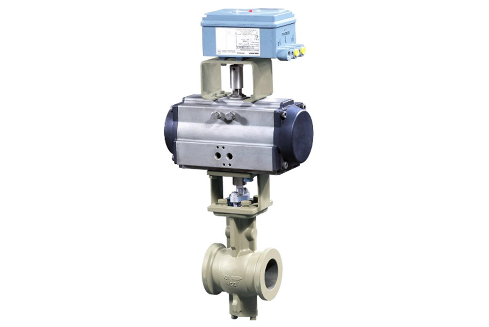
Pneumatic Actuator
GT, DA, and AW type angular stroke pneumatic actuators are the driving devices for pneumatic V-ball valves. They are available in two types: piston-type double-acting and single-acting (spring return type). They feature a compact double (single) piston gear and rack structure, with precise meshing, smooth transmission, large output torque, flexible and stable operation, light weight, and long service life. (The spring of the single-acting type is pre-compressed before installation, making it easy to install and disassemble, and ensuring good safety.)
According to different control and requirements, the following accessories can be selected:
Accessory Options
Cut-off type accessories: Single solenoid valve, double solenoid valve, limit switch position indicator.
Regulating type accessories: Electro-pneumatic positioner, pneumatic positioner, electro-pneumatic converter.
Air source treatment accessories: Air filter regulator, air treatment unit.
Manual mechanism: MNSD manual operating mechanism
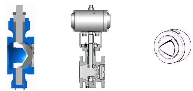
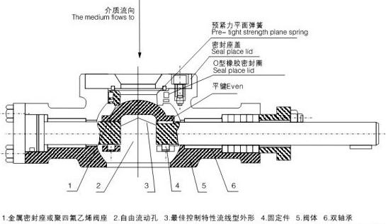
Main Components of V-Ball Valve
| Serial Number | Name | Quantity (pcs) | Material | ||
|---|---|---|---|---|---|
| 1 | Valve Body | 1 | WCB | CF8 | CF8M |
| 2 | Valve Core | 1 | CF8 surface hard chrome plated | CF8 surface hard chrome plated | CF8M surface hard chrome plated |
| 3 | Cylindrical Pin | 2 | 304 | 304 | 316 |
| 4 | Valve Seat | 1 | 304 overlaid with hard alloy | 304 overlaid with hard alloy | 316 |
| 5 | Spring | 1 | 316 | 316 | 316 |
| 6 | O-Ring | 1 | Fluororubber | Fluororubber | Fluororubber |
| 7 | Self-Lubricating Bearing |
|
304 + PTFE | 304 + PTFE | 316 + PTFE |
| 8 | Lower Valve Stem | 1 | 20Cr13 | 304 | 316 |
| 9 | O-Ring | 1 | Fluororubber | Fluororubber | Fluororubber |
| 10 | Rear Gland | 1 | WCB | CF8 | CF8M |
| 11 | Ring Gasket | 1 | PTFE | PTFE | PTFE |
| 12 | Adjusting Shim | 1 | PTFE | PTFE | PTFE |
| 13 | Flat Gasket | 4 | Q235 | 304 | 304 |
| 14 | Bolt | 4 | 25 | 304 | 304 |
| 15 | Stud Bolt | 2 | 25 | 304 | 304 |
| 16 | Self-Lubricating Bearing | 1 | 304 + PTFE | 304 + PTFE | 316 + PTFE |
| 17 | Flat Key | 1 | 20Cr13 | 304 | 316 |
| 18 | Lower Packing | 1 | PTFE | PTFE | PTFE |
| 19 | Middle Packing | 1 set | PTFE | PTFE | PTFE |
| 20 | Upper Packing | 1 | PTFE | PTFE | PTFE |
| 21 | Packing Gland | 1 | WCB | CF8 | CF8M |
| 22 | Nut | 2 | 35 | 304 | 304 |
| 23 | Upper Valve Stem | 1 | 20Cr13 | 304 | 316 |
Applicable Temperature and Medium of Pneumatic V-Ball Valve:
| Material \ Material Code | C | P | R | |
|---|---|---|---|---|
|
Main Components |
Valve Body | WCB | ZG1Cr18Ni9Ti | ZG0Cr18Ni12Mo2Ti |
| Ball | 2Cr13 | ZG1Cr18Ni9Ti | ZG0Cr18Ni12Mo2Ti | |
| Valve Stem | 2Cr13 | 1Cr18Ni9Ti | 0Cr18Ni12Mo2Ti | |
| Sealing Ring | Reinforced PTFE, Parylene, Hard Alloy Steel | |||
| Packing | PTFE, Flexible Graphite | |||
|
Applicable Working Conditions |
Applicable Medium | Water, Steam, Oil | Nitric Acid and Alkali | Acetic Acid |
| Applicable Temperature | -28°C - 500°C | |||
Flow Characteristic (Inherent Flow Characteristic Curve of Pneumatic V-Ball Valve)
Execution Standards of Pneumatic V-Ball Valve
| Design and Manufacturing Standard | Flange Size Standard | Structural Length Standard | Inspection and Test Standard |
|---|---|---|---|
| GB/T12237-89 | JB/T79-94 HG20592 | GB12221-89 | GB/T13927-89 JB/T9092-99 |
| API6D | ANSI B16.5 | ANSI B16.10 | JB/T9092-99 |
| JPI7S-48 | JIS B2212~2214 | JIS B2002 | API598 |
Technical Parameters and Performance Indicators of Pneumatic V-Ball Valve
| Nominal Diameter D (mm) | 25 | 32 | 40 | 50 | 65 | 80 | 100 | 125 | 150 | 200 | 250 | 300 | ||||
|---|---|---|---|---|---|---|---|---|---|---|---|---|---|---|---|---|
| Rated Flow Coefficient Cv | 32 | 47 | 78 | 110 | 170 | 280 | 410 | 750 | 1120 | 1850 | 2950 | 3800 | ||||
| Nominal Pressure PN (MPa) | 1.6, 2.5, 4.0, 6.4 | |||||||||||||||
| Flow Characteristic | Approximately equal percentage (see typical curve), linear characteristic, quick opening | |||||||||||||||
| Valve Plate Rotation Angle (degrees) | 0° - 90° (adjustable) | |||||||||||||||
| Allowable Leakage Class | Soft seal: Zero leakage; Hard seal: ≤10 - 5 rated flow coefficient | |||||||||||||||
| Action Form | Double-acting / Single-acting (spring return type) | |||||||||||||||
| Control Type | Cut-off type / Regulating type | |||||||||||||||
| Actuator | Model | DA series, GT series, AW series, ZSQ series, etc. | ||||||||||||||
| Air Source Pressure | Purified compressed air (nitrogen) 0.3 - 0.7 MPa | |||||||||||||||
| Regulating Type | Input Signal | Current signal: 0 - 10 mA, 4 - 10 mA; Air source signal: 20 - 100 kPa | ||||||||||||||
| Basic Error | With positioner ≤±1.5% | |||||||||||||||
| Hysteresis | With positioner ≤1.5% | |||||||||||||||
| Dead Zone | With positioner ≤0.6% | |||||||||||||||
| Adjustable Ratio | 250:1 | 300:1 | ||||||||||||||
| Cut-off Type | Position Indicator Voltage | AC220V, AC110V, DC24V | ||||||||||||||
| Cut-off Time | 0.5 S | 1.0 S | 2.5 - 4.0 S | 7.0 S | ||||||||||||
Allowable Pressure Difference (MPa) of Pneumatic V-Ball Valve According to Execution Standards
| Nominal Diameter DN (mm) | 25 | 40 | 50 | 65 | 80 | 100 | 125 | 150 | 200 | 250 | 300 | |
|---|---|---|---|---|---|---|---|---|---|---|---|---|
| Rated Flow Coefficient Cv | Hard Seal | 32 | 78 | 90 | 160 | 250 | 360 | 610 | 1120 | 1850 | 2950 | 3700 |
| Soft Seal | 32 | 78 | 90 | 150 | 240 | 345 | 580 | 1080 | 1800 | 2800 | 3550 | |
| Double-acting Pneumatic Actuator | Air source pressure 400 KPa | |||||||||||
| Model |
Torque (N.M) |
Allowable pressure difference for PTFE packing and metal seal, unit: MPa | ||||||||||
| ATD75 | 46.5 | 1.72 | 0.83 | 0.53 | 0.30 | 0.16 |
|
|
|
|
|
|
| ATD88 | 73.2 |
|
1.33 | 1.33 | 0.49 | 0.28 |
|
|
|
|
|
|
| ATD100 | 106 |
|
|
|
|
0.48 | 0.16 |
|
|
|
|
|
| ATD125 | 221 |
|
|
|
|
0.82 | 0.45 | 0.25 | 0.19 |
|
|
|
| ATD160 | 453 |
|
|
|
|
|
0.81 | 0.52 | 0.40 | 0.13 |
|
|
| ATD200 | 850 |
|
|
|
|
|
|
0.9 | 0.69 | 0.60 | 0.42 | 0.31 |
|
Single-acting Pneumatic Actuator |
Air source pressure 400 KPa | |||||||||||
| Model |
Torque (N.M) |
Allowable pressure difference for PTFE packing and metal seal, unit: MPa | ||||||||||
| ATS88 | 44 | 0.60 | 0.24 | 0.16 | 0.08 |
|
|
|
|
|
|
|
| ATS100 | 60.7 | 1.10 | 0.49 | 0.31 | 0.17 | 0.08 |
|
|
|
|
|
|
| ATS125 | 126 |
|
1.21 | 0.79 | 0.44 | 0.25 | 0.06 |
|
|
|
|
|
| ATS160 | 269 |
|
|
|
|
0.56 | 0.20 | 0.10 | 0.08 |
|
|
|
| ATS200 | 467 |
|
|
|
|
0.81 | 0.56 | 0.31 | 0.24 |
|
|
|
| ATS240 | 880 |
|
|
|
|
|
|
0.9 | 0.69 | 0.46 | 0.24 | 0.17 |
Standard Product Cv Value Table of Pneumatic V-Ball Valve:
| Specification | CV Value |
|---|---|
| DN25(1”) | 36 |
| DN32(11/4") | 56 |
| DN40(11/2") | 94 |
| DN50(2”) | 152 |
| DN65(21/2") | 262 |
| DN80(3”) | 358 |
| DNl00(4”) | 540 |
| DN125(5”) | 906 |
| DN150(6”) | 1424 |
| DN200(8”) | 2176 |
| DN250(10”) | 3532 |
| DN300(12") | 5732 |
| DN350(14”) | 8245 |
| DN400(16”) | 10651 |
| DN450(18”) | 12878 |
| DN500(20”) | 16343 |
Maximum Allowable Leakage of Pneumatic V-Ball Valve:
| Specification | Maximum Allowable Leakage of Hard Seal | Maximum Allowable Leakage of Soft Seal Seat |
|---|---|---|
| DN25(1”) | 1.50ml/min | 0.15ml/min |
| DN32(1-1/4") | 1.80ml/min | 0.18ml/min |
| DN40(1-1/2") | 2.40ml/min | 0.24ml/min |
| DN50(2”) | 3.00ml/min | 0.30ml/min |
| DN65(2-1/2") | 3.90ml/min | 0.39ml/min |
| DN80(3”) | 4.80ml/min | 0.48ml/min |
| DNl00(4”) | 6.00ml/min | 0.60ml/min |
| DN125(5”) | 7.50ml/min | 0.75ml/min |
| DN150(6”) | 9.00ml/min | 0.90ml/min |
| DN200(8") | 12.00ml/min | 1.20ml/min |
| DN250(10”) | 15.00ml/min | 1.50ml/min |
| DN300(12”) | 18.00ml/min | 1.80ml/min |
| DN350(14”) | 21.00ml/min | 2.10ml/min |
| DN400(16”) | 24.00ml/min | 2.40ml/min |
| DN450(18”) | 26.00ml/min | 2.60ml/min |
| DN500(20”) | 30.00ml/min | 3.00ml/min |
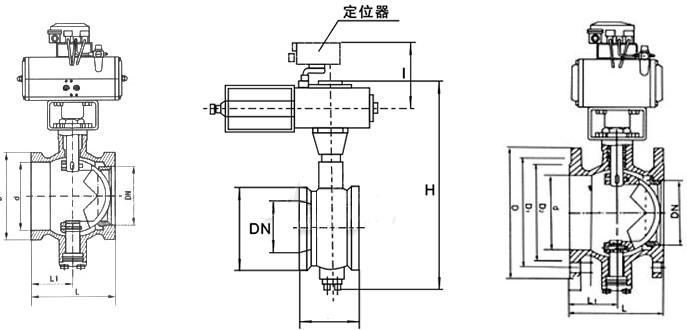
External Dimensions of Pneumatic V-Ball Valve:
| Nominal Diameter | Dimensions (mm) | |||||||
|---|---|---|---|---|---|---|---|---|
| Wafer Type | Flanged Type | |||||||
| D | L | L1 | D | D1 | D2 | L | Z-D | |
| 25 | 64 | 50 | 25 | 115 | 85 | 65 | 102 | 4-14 |
| 40 | 82 | 60 | 25 | 135 | 110 | 85 | 114 | 4-18 |
| 50 | 100 | 75 | 32 | 145 | 125 | 100 | 124 | 4-18 |
| 65 | 120 | 85 | 38 | 160 | 145 | 120 | 145 | 4-18 |
| 80 | 131 | 100 | 45 | 180 | 160 | 135 | 165 | 8-18 |
| 100 | 158 | 115 | 50 | 195 | 180 | 155 | 194 | 8-18 |
| 125 | 180 | 135 | 55 | 215 | 210 | 185 | 213 | 8-18 |
| 150 | 216 | 160 | 65 | 245 | 240 | 210 | 229 | 8-23 |
| 200 | 268 | 200 | 80 | 280 | 295 | 265 | 243 |
12-23 |
(1) Before installation, check that the product model, tag number, and specifications match the requirements. Inspect the entire valve for missing or loose parts.
(2) Prior to installation, clean the pipeline. Ensure there is sufficient straight pipe section at the valve inlet and install a filter. When connecting the valve body to the pipeline flanges, ensure coaxiality.
(3) Thoroughly clean the pipeline before installing the valve.
(4) The installation site should ensure the safety of personnel and equipment, facilitating operation, disassembly, and maintenance.
(5) The valve should be installed vertically upright on horizontal pipelines. If necessary, it can be installed at an angle, but horizontal installation should be avoided. For occasions with heavy valve weight or vibration, use a support frame.
(6) The medium flow direction must align with the arrow on the valve body. The air supply should be dry and oil-free. The valve should be used in environments with temperatures ranging from -20℃ to 55℃.
(1) Cleaning the Valve: For general media, cleaning with water is sufficient. For media harmful to health, first understand their properties and then select an appropriate cleaning method.
(2) Disassembly: Remove rust from exposed rusted parts first. Before derusting, protect the machined surfaces of precision parts such as the valve seat, valve plug, valve stem, and push rod. Use special tools when disassembling the valve seat.
(3) Valve Seat: Minor rust or wear on the sealing surface can be repaired by machining. If damage is severe, replace the seat. However, both repaired and replaced hard sealing surfaces must be lapped.
(4) Valve Stem: If the surface is damaged, it must be replaced.
(5) Damage to Push Rod, Guide, and Sealing Surfaces: Reverse-acting actuators must be replaced; direct-acting actuators can be reused after proper repair.
(6) Compression Spring: If there are cracks or other defects affecting strength, replace it immediately.
(7) Wear Parts: Packing, gaskets, and O-rings must be replaced entirely during each maintenance. Check the valve plug and diaphragm for cracks, aging, or corrosion that may cause future failures. Decide whether to replace them based on inspection results, but the diaphragm service life should not exceed 2-3 years.
(8) When reassembling the valve, ensure alignment. Tighten bolts diagonally and lubricate sliding parts. After reassembly, debug the valve according to the factory test items and methods. During this period, accurately adjust the packing compression force and the valve plug closing position.
-
If the model has not been selected before ordering, please provide us with the operating parameters:
(1) Nominal diameter DN (mm);
(2) Nominal pressure (MPa or bar);
(3) Fluid properties (including medium temperature, viscosity, or acidity/alkalinity);
(4) Pressure before and after the valve (pressure differential);
(5) Requirements for flow characteristics;
(6) Materials of valve body and valve core;
(7) Connection type;
(8) Driving method (provide air supply pressure, driving voltage);
(9) Supporting accessories (for pneumatic valves, it is recommended that users install an air filter triplet and a 2-position 5-way solenoid valve);
(10) On-site working conditions. -
If the product model of our company has been selected by the design unit, please order directly from our production department according to the model;
-
When the application occasion is very important or the pipeline is relatively complex, please provide the design drawings and detailed parameters as much as possible, and our experts will review and check them for you.


