


2. Excellent regulating characteristics: Pneumatic V-ball valves have an approximately equal percentage of inherent flow characteristics and an adjustable ratio of up to 300:1. Therefore, the pneumatic V-type regulating ball valve can provide precise control over a wide range of changes.
3. Maximum flow volume: Due to its streamlined shape and full right angle rotation control, the maximum volume is particularly high, the flow capacity is particularly large, and the flow resistance is small. Therefore, smaller and more economical valve sizes can be used.
4. The pneumatic V-type regulating ball valve adopts a dual bearing structure, with high mechanical stability and low starting torque, ensuring excellent sensitivity and sensing speed of the valve.
5. Maximum reliability (safety): The valve body is a solid and durable structure, which is not affected by pipeline pressure during operation and can prevent valve body leakage.
6. Superior sealing performance of metal valve seat: The pneumatic V-ball valve adopts an elastic movable metal valve seat, which has self compensation function, superior sealing performance, and long service life. In terms of flow direction, the leakage rate is ≤ 10-5 times the rated flow coefficient.
7. Super strong shear ability: When the pneumatic V-shaped regulating ball valve adopts a metal hard seal structure, the valve core and metal seat of the pneumatic V-shaped ball valve generate a strong shear force with the V-shaped notch and valve seat during the rotation process, which can cut off impurities such as fibers and has self-cleaning function to avoid valve jamming.
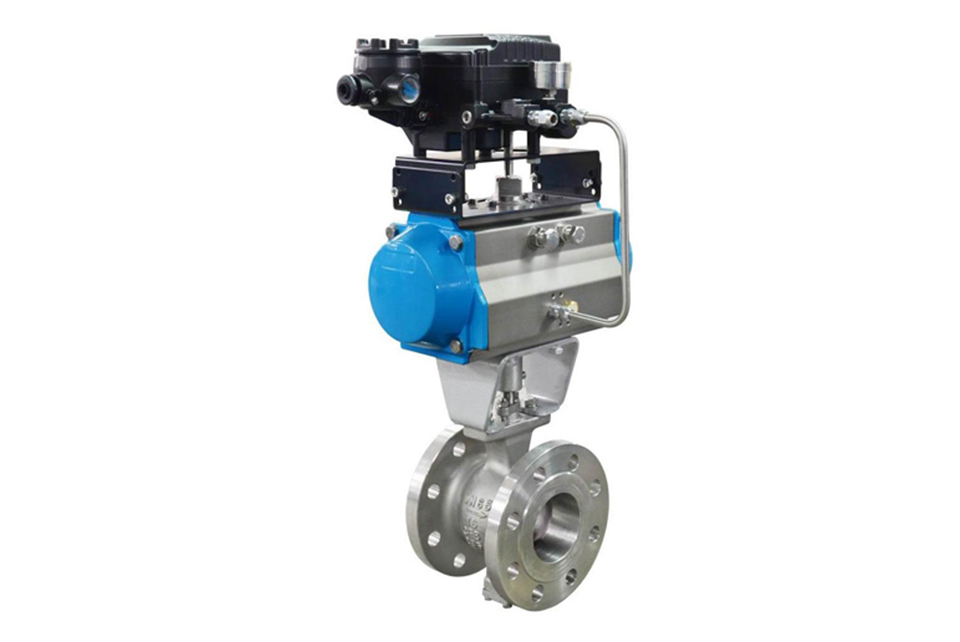
8. The pneumatic actuator adopts a piston type cylinder and a curved arm conversion structure, with a large output torque and small volume precision. The actuator adopts a fully sealed waterproof design with high protection level. The cylinder block adopts a mirror cylinder, oil-free lubrication, low friction coefficient, corrosion resistance, and has super durability and reliability. All transmission bearings adopt boundary self-lubricating bearings without oil lubrication to ensure that the transmission shaft is not worn.
Main performance specifications
| Nominal pressure | 0.6 | 1.0 | 1.6 | 2.0 | 2.5 | 4.0 | 5.0 | 6.4 | 10 | |
|---|---|---|---|---|---|---|---|---|---|---|
| Shell test pressure | 0.9 | 1.5 | 2.4 | 3.0 | 3.8 | 6.0 | 7.5 | 9.6 | 15 | |
| High pressure tight test | 0.66 | 1.1 | 1.8 | 2.2 | 2.8 | 4.4 | 5.5 | 7.1 | 11 | |
| Applicable media & Temperature (℃) | YVQ40Fm type | Water, vapor, pulp, and other solutions, t ≤ 180℃ | ||||||||
| YVQ40Y type |
Natural gas, coal gas, liquefied gas, crude oil, and heavy oil, t ≤ 425℃ |
|||||||||
| YVQ40Ym type | Solutions, ore slurry, alumina powder, coal fines, coal ash, dusty gas, waste residues, etc., t ≤ 300℃ | |||||||||
Main part materials and codes
| Name of part | YCQ40Fm type | YCQ40Y type | YCQ40Ym type |
|---|---|---|---|
| Valve body | Carbon steel WCB / Stainless steel CF8 | Carbon steel WCB / Stainless steel CF8 | Carbon steel WCB / Stainless steel CF8 |
| Valve stem | 2Cr13 / 304 | 2Cr13 / 304 | 2Cr13 / 304 |
| Sealing set for valve body | WCB/CF8 + Cr | WCB/CF8 + Hardened alloy steel | Special hardened alloy steel JK117/17Co alloy |
| Sealing set for valve seat | PTFE / Molon | WCB/CF8 + Hardened alloy steel | Special hardened alloy steel JK117/17Co alloy |
Main parts of pneumatic V-type regulating ball valve
| Serial number | Name | Quantity (pieces) | Material | ||
|---|---|---|---|---|---|
| 1 | Valve body | 1 | WCB | CF8 | CF8M |
| 2 | Valve core | 1 | CF8 surface hard chrome plated | CF8 surface hard chrome plated | CF8M surface hard chrome plated |
| 3 | Cylindrical pin | 2 | 304 | 304 | 316 |
| 4 | Valve seat | 1 | 304 hardfacing carbide | 304 hardfacing carbide | 316 |
| 5 | Spring | 1 | 316 | 316 | 316 |
| 6 | O-ring | 1 | Fluororubber | Fluororubber | Fluororubber |
| 7 | Self-lubricating bearing |
|
304 + PTFE | 304 + PTFE | 316 + PTFE |
| 8 | Lower valve stem | 1 | 20Cr13 | 304 | 316 |
| 9 | O-ring | 1 | Fluororubber | Fluororubber | Fluororubber |
| 10 | Rear gland | 1 | WCB | CF8 | CF8M |
| 11 | Ring gasket | 1 | PTFE | PTFE | PTFE |
| 12 | Adjusting shim | 1 | PTFE | PTFE | PTFE |
| 13 | Flat gasket | 4 | Q235 | 304 | 304 |
| 14 | Bolt | 4 | 25 | 304 | 304 |
| 15 | Stud bolt | 2 | 25 | 304 | 304 |
| 16 | Self-lubricating bearing | 1 | 304 + PTFE | 304 + PTFE | 316 + PTFE |
| 17 | Flat key | 1 | 20Cr13 | 304 | 316 |
| 18 | Lower packing | 1 | PTFE | PTFE | PTFE |
| 19 | Middle packing | 1 set | PTFE | PTFE | PTFE |
| 20 | Upper packing | 1 | PTFE | PTFE | PTFE |
| 21 | Packing gland | 1 | WCB | CF8 | CF8M |
| 22 | Nut | 2 | 35 | 304 | 304 |
| 23 | Upper valve stem | 1 | 20Cr13 | 304 | 316 |
Cv value table of pneumatic V-type regulating ball valve products:
For various types of pneumatic V-type ball valves, including wafer-type V-type ball valves, flange-type V-type ball valves, pneumatic double-actuator V-type ball valves, compact pneumatic V-type regulating valves, and manual worm gear V-type regulating valves. The Cv value of a V-type ball valve represents the flow capacity of the V-type regulating valve for liquids, that is, the flow coefficient. It is generally called the Cv value abroad and the Kv value in China. It is an important parameter of valve products.
Calculation formula: Cv = qv * [ρ * △p0 / (ρ0 * △p)]^0.5
Where: Cv: Flow capacity, USgal/min
qv: Measured water flow, USgal/min
ρ: Measured water density, g/cm³
ρ0: Density of water at 60°F, ρ0 = 1 g/cm³
△p = p1 - p2. p1 and p2 are the pressure differences between the upstream and downstream of the measured component, lbf/in².
| Specification | CV value |
|---|---|
| DN25 (1”) | 36 |
| DN32 (1 1/4") | 56 |
| DN40 (1 1/2") | 94 |
| DN50 (2”) | 152 |
| DN65 (2 1/2") | 262 |
| DN80 (3”) | 358 |
| DN100 (4”) | 540 |
| DN125 (5”) | 906 |
| DN150 (6”) | 1424 |
| DN200 (8”) | 2176 |
| DN250 (10”) | 3532 |
| DN300 (12") | 5732 |
| DN350 (14”) | 8245 |
| DN400 (16”) | 10651 |
| DN450 (18”) | 12878 |
| DN500 (20”) | 16343 |
Maximum allowable leakage of pneumatic V-type regulating ball valve
| Specification | Maximum allowable leakage of hard seal | Maximum allowable leakage of soft seal valve seat |
|---|---|---|
| DN25 (1”) | 1.50 ml/min | 0.15 ml/min |
| DN32 (1 - 1/4") | 1.80 ml/min | 0.18 ml/min |
| DN40 (1 - 1/2") | 2.40 ml/min | 0.24 ml/min |
| DN50 (2”) | 3.00 ml/min | 0.30 ml/min |
| DN65 (2 - 1/2") | 3.90 ml/min | 0.39 ml/min |
| DN80 (3”) | 4.80 ml/min | 0.48 ml/min |
| DN100 (4”) | 6.00 ml/min | 0.60 ml/min |
| DN125 (5”) | 7.50 ml/min | 0.75 ml/min |
| DN150 (6”) | 9.00 ml/min | 0.90 ml/min |
| DN200 (8") | 12.00 ml/min | 1.20 ml/min |
| DN250 (10”) | 15.00 ml/min | 1.50 ml/min |
| DN300 (12”) | 18.00 ml/min | 1.80 ml/min |
| DN350 (14”) | 21.00 ml/min | 2.10 ml/min |
| DN400 (16”) | 24.00 ml/min | 2.40 ml/min |
| DN450 (18”) | 26.00 ml/min | 2.60 ml/min |
| DN500 (20”) | 30.00 ml/min | 3.00 ml/min |
External dimensions of pneumatic V-type regulating ball valve
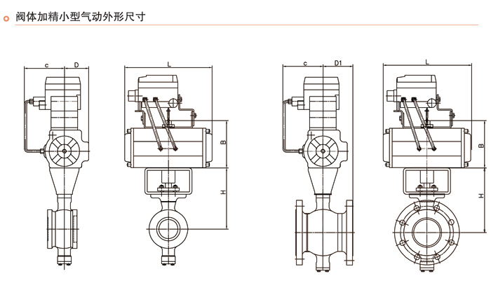
| Nominal pressure PN | Nominal diameter DN (mm) | Dimensions (mm) | |||||||||
|---|---|---|---|---|---|---|---|---|---|---|---|
| L | D | K | d | b | z - d0 | Ws | Hs | Hw | Hd | ||
| 1.6 MPa | 50 | 124 | 165 | 125 | 100 | 16 | 4 - φ18 | 230 | 164 | 260 | 310 |
| 65 | 145 | 185 | 145 | 120 | 18 | 4 - φ18 | 250 | 180 | 275 | 330 | |
| 80 | 165 | 200 | 160 | 135 | 20 | 8 - φ18 | 300 | 200 | 300 | 360 | |
| 100 | 194 | 220 | 180 | 155 | 20 | 8 - φ18 | 320 | 235 | 335 | 390 | |
| 125 | 210 | 250 | 210 | 185 | 22 | 8 - φ18 | 400 | 260 | 355 | 405 | |
| 150 | 229 | 285 | 240 | 210 | 24 | 8 - φ23 | 500 | 280 | 375 | 440 | |
| 200 | 243 | 340 | 295 | 265 | 26 | 12 - φ23 | 800 | 320 | 410 | 470 | |
| 250 | 297 | 405 | 355 | 320 | 30 | 12 - φ25 | 1000 | 355 | 485 | 550 | |
| 300 | 338 | 460 | 410 | 375 | 30 | 12 - φ25 | 1200 | 400 | 530 | 595 | |
| 1.6 MPa | 50 | 124 | 165 | 125 | 100 | 20 | 4 - φ18 | 230 | 164 | 260 | 310 |
| 65 | 145 | 185 | 145 | 120 | 22 | 8 - φ18 | 250 | 180 | 275 | 330 | |
| 80 | 165 | 200 | 160 | 135 | 22 | 8 - φ18 | 300 | 200 | 300 | 360 | |
| 100 | 194 | 230 | 190 | 160 | 24 | 8 - φ23 | 320 | 235 | 335 | 390 | |
| 125 | 210 | 270 | 220 | 188 | 28 | 8 - φ25 | 400 | 260 | 355 | 405 | |
| 150 | 229 | 300 | 250 | 218 | 30 | 8 - φ25 | 500 | 280 | 375 | 440 | |
| 200 | 243 | 360 | 310 | 278 | 34 | 12 - φ25 | 800 | 320 | 410 | 470 | |
| 250 | 297 | 425 | 370 | 332 | 36 | 12 - φ30 | 1000 | 355 | 485 | 550 | |
| 300 | 338 | 485 | 430 | 390 | 40 | 16 - φ30 | 1200 | 400 | 530 | 595 | |
Instructions: 1. The flange connection dimensions of this product are in accordance with the raised face flanges specified in GB/T 9113.1 - 2000 and ASME/ANSI 16.5.
2. The structural length refers to the provisions of GB 12221 - 2005 and ASNE B16.10.
3. The manufacturing and acceptance technical conditions refer to GB12237 - 89 and API 6D.
4. The pressure test is in accordance with the requirements of JB/T9092 - 1999, GB/T13927 - 92, and AP1598.
Note: The flange sealing surface type of this product is the convex face flange specified in GB/T 9113.1 - 2000. When the user's flange sealing form is different from that specified in the table, it should be indicated in the supply contract.
(1) Before installation, check that the product model, tag number, and specifications match the requirements. Inspect the entire valve for missing or loose parts.
(2) Prior to installation, clean the pipeline. Ensure there is sufficient straight pipe section at the valve inlet and install a filter. When connecting the valve body to the pipeline flanges, ensure coaxiality.
(3) Thoroughly clean the pipeline before installing the valve.
(4) The installation site should ensure the safety of personnel and equipment, facilitating operation, disassembly, and maintenance.
(5) The valve should be installed vertically upright on horizontal pipelines. If necessary, it can be installed at an angle, but horizontal installation should be avoided. For occasions with heavy valve weight or vibration, use a support frame.
(6) The medium flow direction must align with the arrow on the valve body. The air supply should be dry and oil-free. The valve should be used in environments with temperatures ranging from -20℃ to 55℃.
(1) Cleaning the Valve: For general media, cleaning with water is sufficient. For media harmful to health, first understand their properties and then select an appropriate cleaning method.
(2) Disassembly: Remove rust from exposed rusted parts first. Before derusting, protect the machined surfaces of precision parts such as the valve seat, valve plug, valve stem, and push rod. Use special tools when disassembling the valve seat.
(3) Valve Seat: Minor rust or wear on the sealing surface can be repaired by machining. If damage is severe, replace the seat. However, both repaired and replaced hard sealing surfaces must be lapped.
(4) Valve Stem: If the surface is damaged, it must be replaced.
(5) Damage to Push Rod, Guide, and Sealing Surfaces: Reverse-acting actuators must be replaced; direct-acting actuators can be reused after proper repair.
(6) Compression Spring: If there are cracks or other defects affecting strength, replace it immediately.
(7) Wear Parts: Packing, gaskets, and O-rings must be replaced entirely during each maintenance. Check the valve plug and diaphragm for cracks, aging, or corrosion that may cause future failures. Decide whether to replace them based on inspection results, but the diaphragm service life should not exceed 2-3 years.
(8) When reassembling the valve, ensure alignment. Tighten bolts diagonally and lubricate sliding parts. After reassembly, debug the valve according to the factory test items and methods. During this period, accurately adjust the packing compression force and the valve plug closing position.
-
If the model has not been selected before ordering, please provide us with the operating parameters:
(1) Nominal diameter DN (mm);
(2) Nominal pressure (MPa or bar);
(3) Fluid properties (including medium temperature, viscosity, or acidity/alkalinity);
(4) Pressure before and after the valve (pressure differential);
(5) Requirements for flow characteristics;
(6) Materials of valve body and valve core;
(7) Connection type;
(8) Driving method (provide air supply pressure, driving voltage);
(9) Supporting accessories (for pneumatic valves, it is recommended that users install an air filter triplet and a 2-position 5-way solenoid valve);
(10) On-site working conditions. -
If the product model of our company has been selected by the design unit, please order directly from our production department according to the model;
-
When the application occasion is very important or the pipeline is relatively complex, please provide the design drawings and detailed parameters as much as possible, and our experts will review and check them for you.


