


Introduction
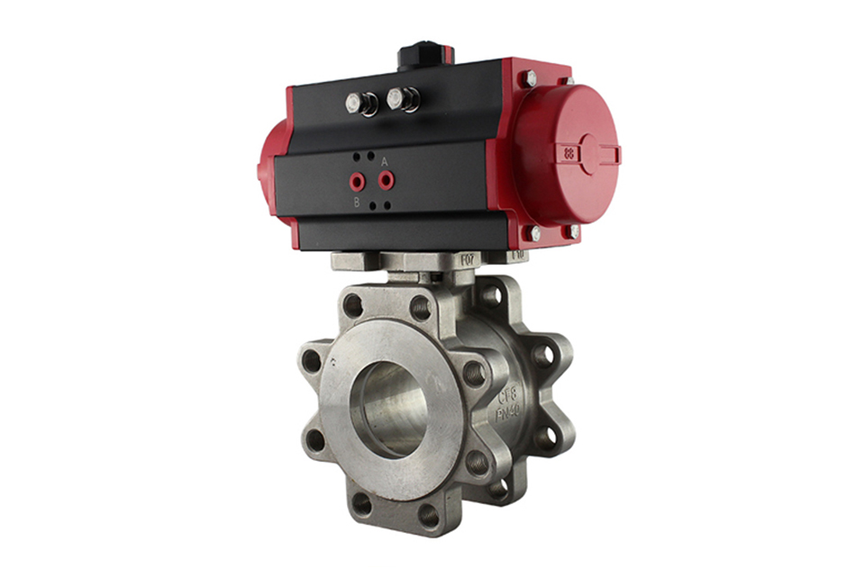
Pneumatic American standard ball valve (ultra-thin type) is composed of a single (double) acting piston pneumatic actuator and an ultra-thin ball valve. The pneumatic ultra-thin American standard ball valve can be equipped with a valve positioner input control signal (4-20mADC or 1-5VDC) to control the operation with a gas source. It can also be equipped with travel limit switches, solenoid valves, pressure reducing valves, and 0.4-0.7MPa gas sources to achieve switch operation, and send two pairs of passive contact signals to indicate the switch of the valve. The pneumatic ultra-thin American standard ball valve (pneumatic clamp ball valve) has a rectangular, V-shaped, and O-shaped core channel shape. This series of products has the characteristics of compact structure, small volume, light weight, and easy installation. Therefore, pneumatic ultra-thin American standard ball valves (pneumatic clamp ball valves) are widely used in fields such as petroleum, chemical, metallurgy, power plants, and light industry.
Technical Parameter
| Test Pressure (MPa) | Nominal Pressure (MPa) | Pressure Class (class) | JIS (K) | |||||
|---|---|---|---|---|---|---|---|---|
| 1.6 | 2.5 | 4.0 | 6.4 | 150 | 300 | 10K | 20K | |
| Strength Test | 2.4 | 3.75 | 6.0 | 9.6 | 3.0 | 7.5 | 2.4 | 3.8 |
| Sealing Test | 1.76 | 2.75 | 4.4 | 7.04 | 2.2 | 5.5 | 1.5 | 2.8 |
| Gas Tightness Test | 0.5 - 0.7 MPa | |||||||
Main Technical Parameters of Pneumatic Ultra-Thin American Standard Ball Valve
Main Performance Indicators
| Nominal Diameter DN (mm) | 15 | 20 | 25 | 32 | 40 | 50 | 65 | 80 | 100 | 125 | 150 | 200 | 250 | 300 |
|---|---|---|---|---|---|---|---|---|---|---|---|---|---|---|
| Allowable Pressure Difference (MPa) | ≤ Nominal Pressure | |||||||||||||
| Action Range | 0 - 90° | |||||||||||||
| Leakage Quantity Q | According to GB/T4213 - 92, less than 0.01% of the rated KV (zero leakage for soft seal) | |||||||||||||
| Basic Error | With positioner: less than ±2% of the full stroke | |||||||||||||
| Hysteresis | With positioner: less than 2% of the full stroke | |||||||||||||
Valve Body
| Valve Body Type | Straight-through Cast Ultra-short Valve |
|---|---|
| Nominal Diameter | DN15 - 300 mm |
| Nominal Pressure | National Standard PN1.6, 2.5, 4.0, 6.4 MPa; American Standard ANSI 150, 300 LB; Japanese Standard JIS 10, 20, 30K |
| Flange Standard | JIS, ANSI, GB, JB, HG, etc. |
| Connection Form | Flange Type, Wafer Type |
| Gland Type | Nut Compression Type |
| Sealing Packing | V-type PTFE Packing, Flexible Graphite Packing, etc. |
Valve Internals
| Valve Core Type | O-type Ball Valve Core |
|---|---|
| Flow Characteristic | Approximately Quick-Opening Type |
Actuator
| Actuator Model | GT, SR, ST, AT, AW Series Single and Double Acting Pneumatic Actuators |
|---|---|
| Supply Pressure | 0.4 - 0.7 MPa |
| Air Source Interface | G1/4″, G1/8″, G3/8″, G1/2″ |
| Ambient Temperature | -20 - +90℃ |
| Action Form |
Single Acting Actuator: Air-to-Close (B) - Valve position open (FO) when air is lost; Air-to-Open (K) - Valve position closed (FC) when air is lost. Double Acting Actuator: Air-to-Close (B) - Valve position remains (FL) when air is lost; Air-to-Open (K) - Valve position remains (FL) when air is lost. |
| Available Accessories |
Positioner, Solenoid Valve, Air Filter Regulator, Position Maintaining Valve, Travel Switch, Valve Position Transmitter, Handwheel Mechanism, etc. |
Valve Installation & Maintenance
Valve Installation:
(1) Before installation, check that the product model, tag number, and specifications match the requirements. Inspect the entire valve for missing or loose parts.
(2) Prior to installation, clean the pipeline. Ensure there is sufficient straight pipe section at the valve inlet and install a filter. When connecting the valve body to the pipeline flanges, ensure coaxiality.
(3) Thoroughly clean the pipeline before installing the valve.
(4) The installation site should ensure the safety of personnel and equipment, facilitating operation, disassembly, and maintenance.
(5) The valve should be installed vertically upright on horizontal pipelines. If necessary, it can be installed at an angle, but horizontal installation should be avoided. For occasions with heavy valve weight or vibration, use a support frame.
(6) The medium flow direction must align with the arrow on the valve body. The air supply should be dry and oil-free. The valve should be used in environments with temperatures ranging from -20℃ to 55℃.
Valve Maintenance:
(1) Cleaning the Valve: For general media, cleaning with water is sufficient. For media harmful to health, first understand their properties and then select an appropriate cleaning method.
(2) Disassembly: Remove rust from exposed rusted parts first. Before derusting, protect the machined surfaces of precision parts such as the valve seat, valve plug, valve stem, and push rod. Use special tools when disassembling the valve seat.
(3) Valve Seat: Minor rust or wear on the sealing surface can be repaired by machining. If damage is severe, replace the seat. However, both repaired and replaced hard sealing surfaces must be lapped.
(4) Valve Stem: If the surface is damaged, it must be replaced.
(5) Damage to Push Rod, Guide, and Sealing Surfaces: Reverse-acting actuators must be replaced; direct-acting actuators can be reused after proper repair.
(6) Compression Spring: If there are cracks or other defects affecting strength, replace it immediately.
(7) Wear Parts: Packing, gaskets, and O-rings must be replaced entirely during each maintenance. Check the valve plug and diaphragm for cracks, aging, or corrosion that may cause future failures. Decide whether to replace them based on inspection results, but the diaphragm service life should not exceed 2-3 years.
(8) When reassembling the valve, ensure alignment. Tighten bolts diagonally and lubricate sliding parts. After reassembly, debug the valve according to the factory test items and methods. During this period, accurately adjust the packing compression force and the valve plug closing position.
Ordering Instructions
When placing an order, please fill in the Specification Sheet or specify the following information:
-
If the model has not been selected before ordering, please provide us with the operating parameters:
(1) Nominal diameter DN (mm);
(2) Nominal pressure (MPa or bar);
(3) Fluid properties (including medium temperature, viscosity, or acidity/alkalinity);
(4) Pressure before and after the valve (pressure differential);
(5) Requirements for flow characteristics;
(6) Materials of valve body and valve core;
(7) Connection type;
(8) Driving method (provide air supply pressure, driving voltage);
(9) Supporting accessories (for pneumatic valves, it is recommended that users install an air filter triplet and a 2-position 5-way solenoid valve);
(10) On-site working conditions. -
If the product model of our company has been selected by the design unit, please order directly from our production department according to the model;
-
When the application occasion is very important or the pipeline is relatively complex, please provide the design drawings and detailed parameters as much as possible, and our experts will review and check them for you.


