


Introduction
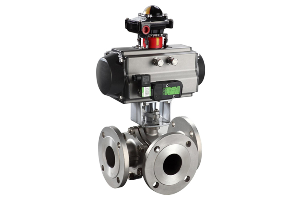
Pneumatic three-way ball valves are divided into L-shaped and T-shaped, and the direction of medium flow is shown in the following figure. The L-shaped three-way ball valve is suitable for switching the flow direction of the medium, which can connect two perpendicular channels. The T-shaped three-way ball valve is suitable for dividing, merging or switching the flow direction of the medium. The T-shaped hole can connect three channels to each other or two of them. The three-way ball valve generally adopts a two seat structure, but can also adopt a four seat structure according to user requirements.
Technical Parameter
Test pressure unit: Mpa Scope of use
| Nominal pressure PN | Maximum working pressure at room temperature | Shell test pressure | Sealing test pressure | High pressure sealing test pressure |
|---|---|---|---|---|
| 1.6 | 1.6 | 2.4 | 0.6 | 1.76 |
| 2.5 | 2.5 | 3.8 | 0.6 | 2.75 |
| 4.0 | 4.0 | 6.0 | 0.6 | 4.4 |
| C1aSSl50 | 2.0 | 3.0 | 0.6 | 2.2 |
| Shell material | Valve seat material | Temperature | Applicable medium |
|---|---|---|---|
| Carbon steel C-type | PTFE | ≤150℃ | Water/Steam |
| PPL | ≤300℃ | Oil crystals, etc | |
| Chromium nickel titanium steel P-type | PTFE | ≤150℃ | Nitric Acid |
| PPL | ≤200℃ |
|
|
| Ci Ni Mo Ti Steel | PTFE | ≤150℃ | Acetic acid |
| PPL | ≤200℃ |
|
Material for main parts
| Valve body/valve cover | GB | WCB | ZGlCrl8Ni9Ti | ZGOCfl8Nil2M02Ti | |||
|---|---|---|---|---|---|---|---|
| ASTM | WCB | CF8 | CF8M | ||||
| Sphere | GB | 2Cfl3 | 1Cfl8Ni9Ti | 0Cfl8Ni12M02Ti | |||
| ASTM | 420 | 304 | 316 | ||||
| Valve stem | GB | 2Crl3 | 1Crl8Ni9Ti | 0Crl8Ni12M02Ti | |||
| ASTM | 420 | 304 | 316 | ||||
| Valve seat/sealing surface | GB | PTFE | PPL | PTFE | PPL | PTFE | PPL |
| ASTM | PTFE | PPL | PTFE | PPL | PTFE | PPL | |
| Filler | GB | PTFE | Flexible graphite | PTFE | Flexible graphite | PTFE | Flexible graphite |
| ASTM | PTFE | Flexible graphite | PTFE | Flexible graphite | PTFE | Flexible graphite | |
| Bolt | GB | 35 | 0Crl8Ni9 | 0Crl8Ni9 | |||
| ASTM | A193B7 | A320-B8 | A320-B8 | ||||
| Nut | GB | 45 | 0Cfl8Ni9 | 0Crl8Ni9 | |||
| ASTM | A1942H | A194-8 | A194-8 | ||||
Main connection dimensions
| Nominal pressure PN | Nominal diameter DN | Size (mm) | |||||||||
|---|---|---|---|---|---|---|---|---|---|---|---|
| L | L0 | D | K | d | Y | b | z-do | Hw | Hd | ||
| 1.6MPa | 50 | 260 | 130 | 165 | 125 | 100 |
|
16 | 4-ф18 | 205 | 265 |
| 65 | 320 | 160 | 185 | 145 | 120 |
|
18 | 4-ф18 | 245 | 295 | |
| 80 | 320 | 160 | 200 | 160 | 135 |
|
20 | 8-ф18 | 305 | 345 | |
| 100 | 370 | 185 | 220 | 180 | 155 |
|
20 | 8-ф18 | 340 | 420 | |
| 125 | 510 | 255 | 250 | 210 | 185 |
|
22 | 8-ф18 | 425 | 465 | |
| 150 | 510 | 255 | 285 | 240 | 2'0 |
|
24 | 8-ф23 | 450 | 505 | |
| 200 | 580 | 290 | 340 | 295 | 265 |
|
26 | 12-ф23 | 480 | 525 | |
| 250 | 670 | 335 | 405 | 355 | 320 |
|
30 | 12-ф25 | 530 | 565 | |
| 300 | 760 | 380 | 460 | 410 | 375 |
|
30 | 12-ф25 | 585 | 630 | |
| 350 | 850 | 425 | 520 | 470 | 435 |
|
34 | 16-ф25 | 625 | 675 | |
| 400 | 980 | 490 | 580 | 525 | 485 |
|
36 | 16-ф30 | 670 | 710 | |
| 450 | 1080 | 540 | 640 | 585 | 545 |
|
40 | 20-ф30 | 705 | 770 | |
| 500 | 1220 | 610 | 715 | 650 | 608 |
|
44 | 20-ф34 | 765 | 825 | |
| 600 | 1360 | 680 | 840 | 770 | 718 |
|
48 | 20-ф41 | 840 | 945 | |
| 700 | 1750 | 875 | 910 | 840 | 788 |
|
50 | 24-ф41 | 1050 | 1110 | |
| 800 | 1850 | 925 | 1025 | 950 | 898 |
|
52 | 24-ф41 | 1125 | 1220 | |
| 900 | 2050 | 1025 | 1125 | 1050 | 998 |
|
54 | 28-ф41 | 1260 | 1315 | |
| 1000 | 2150 | 1075 | 1255 | 1170 | 1110 |
|
56 | 28-ф48 | 1325 | 1385 | |
| 1200 | 2450 | 1225 | 1485 | 1390 | 1325 |
|
58 | 32-ф54 | 1395 | 1450 | |
| 2.5MPa | 50 | 260 | 130 | 165 | 125 | 100 |
|
20 | 4-ф18 | 205 | 265 |
| 65 | 320 | 160 | 185 | 145 | 120 |
|
22 | 8-ф18 | 245 | 295 | |
| 80 | 320 | 160 | 200 | 160 | 135 |
|
22 | 8-ф18 | 305 | 345 | |
| 100 | 370 | 185 | 230 | 190 | 160 |
|
24 | 8-ф23 | 340 | 420 | |
| 125 | 510 | 255 | 270 | 220 | 188 |
|
28 | 8-ф25 | 405 | 465 | |
| 150 | 510 | 255 | 300 | 250 | 218 |
|
30 | 8-ф25 | 450 | 505 | |
| 200 | 580 | 290 | 360 | 310 | 278 |
|
34 | 12-ф25 | 480 | 525 | |
| 250 | 670 | 335 | 425 | 370 | 332 |
|
36 | 12-ф30 | 530 | 565 | |
| 300 | 760 | 380 | 485 | 430 | 390 |
|
40 | 16-ф30 | 585 | 630 | |
| 350 | 850 | 425 | 555 | 490 | 448 |
|
44 | 16-ф34 | 625 | 675 | |
| 400 | 980 | 490 | 620 | 550 | 505 |
|
48 | 16-ф34 | 670 | 710 | |
| 450 | 1080 | 540 | 670 | 600 | 555 |
|
50 | 20-ф34 | 705 | 770 | |
| 500 | 1220 | 610 | 730 | 660 | 610 |
|
52 | 20-ф41 | 765 | 825 | |
| 600 | 1360 | 680 | 845 | 770 | 718 |
|
56 | 20-041 | 840 | 945 | |
| 700 | 1750 | 875 | 960 | 875 | 815 |
|
60 | 24-ф48 | 1050 | 1110 | |
| 800 | 1850 | 925 | 1085 | 990 | 930 |
|
64 | 24-ф48 | 1125 | 1220 | |
| 900 | 2050 | 1025 | 1185 | 1090 | 1025 |
|
66 | 28-ф54 | 1260 | 1315 | |
| 1000 | 2150 | 1075 | 1320 | 1210 | 1140 |
|
68 | 28-ф58 | 1325 | 1385 | |
| 1200 | 2450 | 1225 | 1520 | 1420 | 1350 |
|
72 | 32-ф58 | 1395 | 1450 | |
| 4.0MPa | 50 | 260 | 130 | 165 | 125 | 100 | 88 | 20 | 8-ф18 | 245 | 285 |
| 65 | 320 | 160 | 185 | 145 | 120 | 110 | 22 | 8-ф18 | 265 | 315 | |
| 80 | 320 | 160 | 200 | 160 | 135 | 121 | 22 | 8-ф18 | 320 | 365 | |
| 100 | 370 | 185 | 235 | 190 | 160 | 150 | 24 | 8-ф23 | 355 | 465 | |
| 125 | 510 | 255 | 270 | 220 | 188 | 176 | 28 | 8-ф25 | 425 | 495 | |
| 150 | 510 | 255 | 300 | 250 | 218 | 204 | 30 | 8-ф25 | 470 | 535 | |
| 200 | 580 | 290 | 375 | 320 | 282 | 260 | 38 | 12-ф30 | 480 | 565 | |
| 250 | 670 | 335 | 450 | 385 | 345 | 313 | 42 | 12-ф34 | 530 | 605 | |
| 300 | 760 | 380 | 515 | 450 | 408 | 364 | 46 | 16-ф34 | 585 | 675 | |
| 350 | 850 | 425 | 580 | 510 | 465 | 422 | 52 | 16-ф34 | 625 | 705 | |
| 400 | 980 | 490 | 660 | 585 | 535 | 474 | 58 | 16-ф41 | 670 | 745 | |
| 450 | 1080 | 540 | 685 | 610 | 560 | 524 | 60 | 20-ф41 | 705 | 795 | |
| 500 | 1220 | 610 | 755 | 670 | 612 | 576 | 62 | 20-ф48 | 765 | 855 | |
| 600 | 1360 | 680 | 890 | 795 | 730 | 678 | 62 | 20-ф54 | 840 | 985 | |
| C1aSS150 | 2" | 260 | 130 | 152 | 120.5 | 92 |
|
16 | 伞φ19 | 205 | 265 |
| 2 1/2" | 320 | 160 | 178 | 139.5 | 105 |
|
18 | 4-ф19 | 245 | 295 | |
| 3" | 320 | 160 | 190 | 152.5 | 127 |
|
19 | 4-ф19 | 305 | 345 | |
| 4" | 370 | 185 | 229 | 190.5 | 157 |
|
24 | 8-ф19 | 340 | 420 | |
| 5" | 510 | 255 | 254 | 216 | 186 |
|
24 | 8-ф22 | 425 | 465 | |
| 6" | 510 | 255 | 279 | 241.5 | 216 |
|
26 | 8-ф22 | 450 | 505 | |
| 8" | 580 | 290 | 343 | 298.5 | 270 |
|
29 | 8-ф22 | 530 | 525 | |
| 10" | 670 | 335 | 406 | 362 | 324 |
|
31 | 12-ф25 | 630 | 565 | |
| 12" | 760 | 380 | 483 | 432 | 381 |
|
32 | 12-ф25 | 680 | 630 | |
| 14" | 850 | 425 | 533 | 476 | 413 |
|
35 | 12-ф29 | 625 | 675 | |
| 16" | 980 | 490 | 597 | 540 | 470 |
|
37 | 16-ф29 | 670 | 710 | |
| 18" | 1080 | 540 | 635 | 578 | 533 |
|
40 | 16-ф32 | 705 | 770 | |
| 20" | 1220 | 610 | 699 | 635 | 584 |
|
43 | 20-ф32 | 765 | 825 | |
| 24" | 1360 | 680 | 813 | 749.5 | 692 |
|
48 | 20。ф35 | 840 | 945 | |
| 28" | 1750 | 875 | 927 | 864 | 800 |
|
71 | 28-ф35 | 1050 | 1110 | |
| 32" | 1850 | 925 | 1060 | 978 | 914 |
|
81 | 28-ф41 | 1125 | 1220 | |
| 36" | 2050 | 1025 | 1168 | 1086 | 1022 |
|
90 | 32-ф41 | 1260 | 1315 | |
| 40" | 2150 | 1075 | 1289 | 1200 | 1124 |
|
90 | 36-ф41 | 1325 | 1385 | |
| 48" | 2450 | 1225 | 1511 | 1422 | 1359 |
|
108 | 44-ф41 | 1395 | 1450 | |
Valve Installation & Maintenance
Valve Installation:
(1) Before installation, check that the product model, tag number, and specifications match the requirements. Inspect the entire valve for missing or loose parts.
(2) Prior to installation, clean the pipeline. Ensure there is sufficient straight pipe section at the valve inlet and install a filter. When connecting the valve body to the pipeline flanges, ensure coaxiality.
(3) Thoroughly clean the pipeline before installing the valve.
(4) The installation site should ensure the safety of personnel and equipment, facilitating operation, disassembly, and maintenance.
(5) The valve should be installed vertically upright on horizontal pipelines. If necessary, it can be installed at an angle, but horizontal installation should be avoided. For occasions with heavy valve weight or vibration, use a support frame.
(6) The medium flow direction must align with the arrow on the valve body. The air supply should be dry and oil-free. The valve should be used in environments with temperatures ranging from -20℃ to 55℃.
Valve Maintenance:
(1) Cleaning the Valve: For general media, cleaning with water is sufficient. For media harmful to health, first understand their properties and then select an appropriate cleaning method.
(2) Disassembly: Remove rust from exposed rusted parts first. Before derusting, protect the machined surfaces of precision parts such as the valve seat, valve plug, valve stem, and push rod. Use special tools when disassembling the valve seat.
(3) Valve Seat: Minor rust or wear on the sealing surface can be repaired by machining. If damage is severe, replace the seat. However, both repaired and replaced hard sealing surfaces must be lapped.
(4) Valve Stem: If the surface is damaged, it must be replaced.
(5) Damage to Push Rod, Guide, and Sealing Surfaces: Reverse-acting actuators must be replaced; direct-acting actuators can be reused after proper repair.
(6) Compression Spring: If there are cracks or other defects affecting strength, replace it immediately.
(7) Wear Parts: Packing, gaskets, and O-rings must be replaced entirely during each maintenance. Check the valve plug and diaphragm for cracks, aging, or corrosion that may cause future failures. Decide whether to replace them based on inspection results, but the diaphragm service life should not exceed 2-3 years.
(8) When reassembling the valve, ensure alignment. Tighten bolts diagonally and lubricate sliding parts. After reassembly, debug the valve according to the factory test items and methods. During this period, accurately adjust the packing compression force and the valve plug closing position.
Ordering Instructions
When placing an order, please fill in the Specification Sheet or specify the following information:
-
If the model has not been selected before ordering, please provide us with the operating parameters:
(1) Nominal diameter DN (mm);
(2) Nominal pressure (MPa or bar);
(3) Fluid properties (including medium temperature, viscosity, or acidity/alkalinity);
(4) Pressure before and after the valve (pressure differential);
(5) Requirements for flow characteristics;
(6) Materials of valve body and valve core;
(7) Connection type;
(8) Driving method (provide air supply pressure, driving voltage);
(9) Supporting accessories (for pneumatic valves, it is recommended that users install an air filter triplet and a 2-position 5-way solenoid valve);
(10) On-site working conditions. -
If the product model of our company has been selected by the design unit, please order directly from our production department according to the model;
-
When the application occasion is very important or the pipeline is relatively complex, please provide the design drawings and detailed parameters as much as possible, and our experts will review and check them for you.


