


1. Compact and lightweight, easy to disassemble and repair, and can be installed in any position.
2. The structure is simple and compact, with low operating torque and quick opening of 90 ° rotation.
3. The flow characteristics tend towards a straight line, with good regulation performance.
4. The connection between the butterfly plate and the valve stem adopts a pin free structure, which overcomes the possible internal leakage points.
5. The outer circle of the butterfly plate adopts a spherical shape, which improves the sealing performance and extends the service life of the valve. It can be opened and closed under pressure for more than 50000 times and still maintain zero leakage.
6. The sealing components are replaceable and the sealing is reliable, achieving bidirectional sealing.
7. Butterfly plates can be coated with coatings such as nylon or polytetrafluoroethylene according to user requirements.
8. This valve can be designed for flange connection and clamp connection.
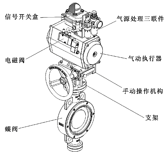
9. The driving mode can be selected as manual, electric or pneumatic
Performance Specifications
| Nominal Diameter DN | 50 | 65 | 80 | 100 | 15 | 10 | 200 | 250 | 300 | 350 | 400 | 450 | 500 | 600 | 700 | 800 | 900 | 1000 |
|---|---|---|---|---|---|---|---|---|---|---|---|---|---|---|---|---|---|---|
| Flow Coefficient (Kv) | 110 | 180 | 232 | 368 | 55 | 75 | 1240 | 2025 | 2712 | 3875 | 5038 | 6330 | 7755 | 11886 | 15375 | 19380 | 25695 | 31365 |
| Action Range | 0-90° | |||||||||||||||||
| Allowable Pressure Difference ΔP | Less than Nominal Pressure (1.6MPa) | |||||||||||||||||
| Leakage | According to GB/T4213-92, 10-4 of Kv value | |||||||||||||||||
| Basic Error | ±2.5% with Positioner | |||||||||||||||||
| Hysteresis | 2.5% with Positioner | |||||||||||||||||
| Dead Band | 1% with Positioner | |||||||||||||||||
| Ambient Temperature | -20℃~+90℃ | |||||||||||||||||
*Note: The structural length and connecting flange dimensions of the pneumatic wafer butterfly valve can be designed and manufactured according to user requirements.
Material Selection and Applicable Temperature
| Material Type | Neoprene | Nitrile Rubber | EPDM Rubber | Polytetrafluoroethylene | Silicone Rubber | Fluororubber | Natural Rubber | Nylon |
|---|---|---|---|---|---|---|---|---|
| English Abbreviation | CR | NBR | EPDM | PTFE | SI | VITON | NR | PA |
| Model Code | X or J | XA or JA | XB or JB | F or XC, JC | XD or JD | XE or JE | X1 | N |
| Maximum Temperature Resistance | 82℃ | 93℃ | 150℃ | 232℃ | 250℃ | 204℃ | 85℃ | 93℃ |
| Minimum Temperature Resistance | -40℃ | -40℃ | -40℃ | -268℃ | -70℃ | -23℃ | -20℃ | -73℃ |
| Applicable Operating Temperature | 0~+80℃ | -20~+82℃ | -40~+125℃ | -30~+150℃ | -70~+150℃ | -23~+150℃ | -20~+85℃ | -30~+93℃ |
Main Part Material Table
| Model | D71X-6 | D71X-10 | D71X-16Q | |
|---|---|---|---|---|
| Operating Pressure (MPa) | 0.6 | 1.0 | 1.6 | |
| Applicable Temperature (℃) | -20~80 | |||
| Applicable Medium | Water, Oil, Seawater, Steam and Various Organic Solvents | |||
| Material | Valve Body | Gray Cast Iron | Ductile Cast Iron | |
| Valve Plate | Gray Cast Iron | Gray Cast Iron | ||
| Valve Stem | Stainless Steel | Stainless Steel | ||
| Sealing Surface | NBR, EPDM | Fluororubber | ||
| Packing | V-shaped Combined Seal Ring, Flexible Graphite | |||
Note: The materials of the main parts and sealing rings of the pneumatic wafer butterfly valve series can be selected according to the actual working conditions or user requirements.
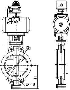
External Dimensions and Connection Dimensions D671 (X, J, F, F4) - 6.0, 1D (0.6, 1.0MPa)
| Nominal Diameter | L | (D671X-6 Type) 0.6MPa | (D671X-10 Type) 1.0MPa | (D671X-16 Type) 1.6MPa | H | H1 | |||
|---|---|---|---|---|---|---|---|---|---|
| D1 | Z-d | D1 | Z-d | D1 | Z-d | ||||
| 50 | 43 | 110 | 4-14 | 120 | 4-23 | 120 | 4-23 | 160 | 80 |
| 65 | 46 | 130 | 4-14 | 136 | 4-26.5 | 136 | 4-26.5 | 175 | 88 |
| 80 | 46 | 150 | 4-18 | 160 | 4-18 | 160 | 4-18 | 180 | 96 |
| 100 | 52 | 170 | 4-18 | 185 | 4-24.5 | 185 | 4-24.5 | 200 | 115 |
| 125 | 56 | 200 | 4-18 | 215 | 4-23 | 210 | 4-23 | 213 | 128 |
| 150 | 56 | 225 | 4-18 | 238 | 4-25 | 238 | 4-25 | 225 | 140 |
| 200 | 60 | 280 | 4-18 | 295 | 4-25 | 295 | 4-25 | 260 | 175 |
| 250 | 68 | 335 | 4-18 | 357 | 4-29 | 357 | 4-29 | 290 | 202 |
| 300 | 78 | 395 | 4-23 | 407 | 4-29 | 407 | 4-29 | 330 | 242 |
| 350 | 78 | 445 | 4-23 | 467 | 4-30 | 467 | 4-30 | 360 | 266 |
| 400 | 102 | 495 | 4-23 | 515 | 4-26 | 525 | 4-26 | 390 | 298 |
| 450 | 114 | 550 | 4-23 | 565 | 4-26 | 585 | 4-26 | 410 | 315 |
| 500 | 127 | 600 | 4-23 | 620 | 4-26 | 650 | 4-26 | 430 | 348 |
| 600 | 154 | 705 | 4-25 | 725 | 4-30 | 770 | 4-30 | 490 | 400 |
| 700 | 165 | 810 | 4-25 | 840 | 4-30 | 840 | 4-30 | 550 | 520 |
| 800 | 190 | 920 | 4-30 | 950 | 4-34 | 950 | 4-34 | 610 | 591 |
| 900 | 203 | 1020 | 4-27 | 1050 | 4-30 | 1050 | 4-30 | 680 | 660 |
| 1000 | 216 | 1120 | 4-30 | 1160 | 4-30 | 1170 | 4-30 | 730 | 670 |
| 1200 | 254 | 1340 | 4-45 | 1380 | 4-45 | 1390 | 4-45 | 835 | 780 |
| 1400 | 270 | 1560 | 4-45 | 1590 | 4-45 | 1590 | 4-45 | 960 | 895 |
| 1600 | 318 | 1760 | 4-52 | 1820 | 4-52 | 1820 | 4-52 | 1200 | 1020 |
(1) Before installation, check that the product model, tag number, and specifications match the requirements. Inspect the entire valve for missing or loose parts.
(2) Prior to installation, clean the pipeline. Ensure there is sufficient straight pipe section at the valve inlet and install a filter. When connecting the valve body to the pipeline flanges, ensure coaxiality.
(3) Thoroughly clean the pipeline before installing the valve.
(4) The installation site should ensure the safety of personnel and equipment, facilitating operation, disassembly, and maintenance.
(5) The valve should be installed vertically upright on horizontal pipelines. If necessary, it can be installed at an angle, but horizontal installation should be avoided. For occasions with heavy valve weight or vibration, use a support frame.
(6) The medium flow direction must align with the arrow on the valve body. The air supply should be dry and oil-free. The valve should be used in environments with temperatures ranging from -20℃ to 55℃.
(1) Cleaning the Valve: For general media, cleaning with water is sufficient. For media harmful to health, first understand their properties and then select an appropriate cleaning method.
(2) Disassembly: Remove rust from exposed rusted parts first. Before derusting, protect the machined surfaces of precision parts such as the valve seat, valve plug, valve stem, and push rod. Use special tools when disassembling the valve seat.
(3) Valve Seat: Minor rust or wear on the sealing surface can be repaired by machining. If damage is severe, replace the seat. However, both repaired and replaced hard sealing surfaces must be lapped.
(4) Valve Stem: If the surface is damaged, it must be replaced.
(5) Damage to Push Rod, Guide, and Sealing Surfaces: Reverse-acting actuators must be replaced; direct-acting actuators can be reused after proper repair.
(6) Compression Spring: If there are cracks or other defects affecting strength, replace it immediately.
(7) Wear Parts: Packing, gaskets, and O-rings must be replaced entirely during each maintenance. Check the valve plug and diaphragm for cracks, aging, or corrosion that may cause future failures. Decide whether to replace them based on inspection results, but the diaphragm service life should not exceed 2-3 years.
(8) When reassembling the valve, ensure alignment. Tighten bolts diagonally and lubricate sliding parts. After reassembly, debug the valve according to the factory test items and methods. During this period, accurately adjust the packing compression force and the valve plug closing position.
-
If the model has not been selected before ordering, please provide us with the operating parameters:
(1) Nominal diameter DN (mm);
(2) Nominal pressure (MPa or bar);
(3) Fluid properties (including medium temperature, viscosity, or acidity/alkalinity);
(4) Pressure before and after the valve (pressure differential);
(5) Requirements for flow characteristics;
(6) Materials of valve body and valve core;
(7) Connection type;
(8) Driving method (provide air supply pressure, driving voltage);
(9) Supporting accessories (for pneumatic valves, it is recommended that users install an air filter triplet and a 2-position 5-way solenoid valve);
(10) On-site working conditions. -
If the product model of our company has been selected by the design unit, please order directly from our production department according to the model;
-
When the application occasion is very important or the pipeline is relatively complex, please provide the design drawings and detailed parameters as much as possible, and our experts will review and check them for you.


