


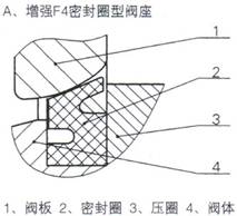
Double eccentric installation of valve plate, when closed, the valve plate expands outward to achieve the best peripheral sealing state; When opened, the valve plate and sealing ring quickly detach, effectively preventing the sealing ring from wearing out;
The sealing ring design is innovative, concise, and maintenance free:
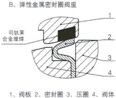
There are two types of sealing ring forms to choose from: soft sealing and metal sealing, to meet the requirements of different working conditions;
Due to the use of an eccentric structure, the operating torque is greatly reduced;
Low flow resistance, high rated flow coefficient, about three times that of a single seat valve of the same caliber;
Strong self-cleaning ability and long service life;
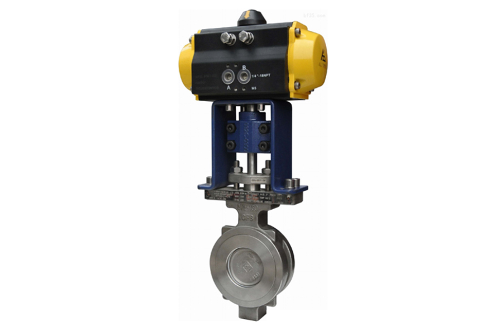
The valve adopts a flange free structure, and the process pipeline adopts a clamp type installation;
The three major types of standard actuators (pneumatic piston type, pneumatic diaphragm type, and electric) are interchangeable.
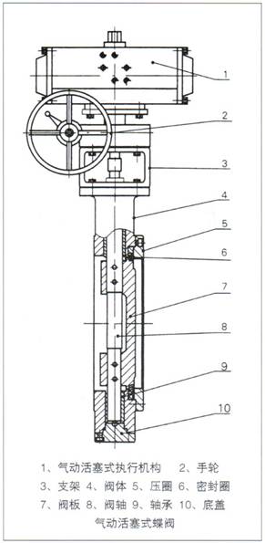
Main component materials
Valve body: ZG230 - 450, ZG1Cr18Ni9Ti
Valve plate: ZG1Cr18Ni9Ti
Valve shaft: 3Cr13, ZG1Cr18Ni9Ti
Pressure ring: ZG230 - 450, 1Cr18Ni9Ti
Sealing ring: Reinforced polytetrafluoroethylene, 1Cr18Ni9Ti, 17 - 4PH
Packing: Polytetrafluoroethylene, flexible graphite
Guide sleeve: QA19 - 4, 0Cr18Ni9, composite material
Bracket: ZG230 - 450
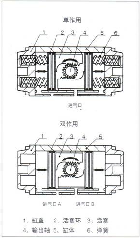
The pneumatic piston actuator adopts a double - piston rack and pinion mechanism, which has the advantages of small structure, large output, accurate action, and strong interchangeability between single - acting and double - acting.
Basic structure and sealing ring form
|
|
|
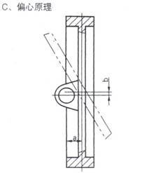
The eccentric butterfly valve is designed with two eccentricities; the rotation axis of the valve plate deviates from the center of the cross - section of the valve plate seal (a); the rotation axis deviates from the center of the pipeline (b). When opening, all points on the sealing surface of the valve plate are separated from the sealing ring at the same time; there is no extrusion between the rotation of the valve plate and the seal. The service life of the sealing ring is improved. The sealing surface can maintain an automatically adjustable optimal effect. Rubber and reinforced polytetrafluoroethylene sealing rings are used, with a leakage class of VI, achieving zero leakage. The elastic metal stainless - steel sealing ring can be used in high - temperature and other more demanding applications. |
Main performance indicators
| Serial number | Item | Pneumatic butterfly valve | Electric butterfly valve | ||
|---|---|---|---|---|---|
| Equipped with pneumatic diaphragm actuator | Equipped with pneumatic piston actuator | ||||
| 1 | Basic error < (1%) | ±2.0 | ±2.5 | ±2.5 | |
| 2 | Hysteresis < (1%) | 2.0 | 2.5 | 2.0 | |
| 3 | Dead zone (1%) | 1.0 | 2.0 | 3.0 | |
| 4 | Start - end point deviation < (1%) | Start point | ±2.0 | ±2.0 | ±1.5 |
| End point | |||||
| 5 | Rated rotation angle deviation < (1%) | ±2.5 (±6 for two - position type) | ±0.5 | ||
| 6 | Rated flow coefficient deviation < (1%) | ±10 | |||
Note: The performance indicators of this product comply with GB/T - 4213.
Specifications and technical parameters
| Nominal diameter DN (mm) | 50 | 65 | 80 | 100 | 125 | 150 | 200 | 250 | 300 | 350 | 400 | 450 | 500 | 600 | 700 | 800 | 900 | 1000 | 1200 | ||
|---|---|---|---|---|---|---|---|---|---|---|---|---|---|---|---|---|---|---|---|---|---|
| Rated flow coefficient Kv | 100 | 150 | 200 | 405 | 620 | 1150 | 2030 | 3150 | 4550 | 6200 | 8100 | 10260 | 13500 | 19800 | 27000 | 35700 | 44600 | 55080 | 81000 | ||
| Nominal pressure PN (MPa) | 0.6 1.0 1.6 4.0 (DN50 - 400) | ||||||||||||||||||||
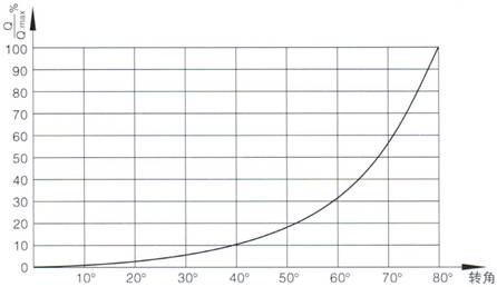
| Flow characteristic | Approximately equal percentage | ||||||||||||||||||||
| Rated rotation angle (°) | 80 | ||||||||||||||||||||
| Pneumatic diaphragm type | See Tables 5 - 8 for details. | ||||||||||||||||||||
| Actuator used | Pneumatic piston type | Single - acting model torque (Nm) Double - acting model torque (Nm) | |||||||||||||||||||
| Electric actuator | Code | ||||||||||||||||||||
| Torque (Nm) | |||||||||||||||||||||
| Air source pressure (MPa) | 0.25 - 0.4 (pneumatic diaphragm type), 0.4 - 0.6 (pneumatic piston type) | ||||||||||||||||||||
| Power supply (electric) | 220V.AC or 380V.AC | ||||||||||||||||||||
| Spring range of pneumatic diaphragm type (MPa) | 40 - 200, 80 - 240 | ||||||||||||||||||||
| Input signal | 4 - 20mA, 0 - 10mA, 1 - 5V.DC or split - range control with the above signals | ||||||||||||||||||||
Overall working temperature range · Valve seat leakage
Valve body material is cast steel
| Valve body | |||||
|---|---|---|---|---|---|
| Valve plate | 1Cr18Ni9Ti hard - chrome plated | 1Cr18Ni9Ti hard - chrome plated | 1Cr18Ni9Ti hard - chrome plated | 1Cr18Ni9Ti hard - chrome plated | 1Cr18Ni9Ti + Stellite alloy |
| Sealing ring | Rubber | Reinforced tetrafluoroethylene | Stainless steel | Stainless steel | Stainless steel |
| Pressure ring | 1Cr18Ni9Ti | 1Cr18Ni9Ti | 1Cr18Ni9Ti | 1Cr18Ni9Ti | 1Cr18Ni9Ti |
| Packing | Polytetrafluoroethylene | Polytetrafluoroethylene | Polytetrafluoroethylene | Flexible graphite | Flexible graphite |
| Gasket | ×B450/F4 | ×B450/F4 | ×B450/F4 | Graphite spiral wound gasket | Graphite spiral wound gasket |
| Leakage class | VI class | VI class | IV class | IV class | V class |
| Valve seat leakage (l/h) | Micro - bubble level ① | Micro - bubble level ① | 10 - 4×Kv | 10 - 4×Kv | 1.8×10 - 7△P×D |
| Operating temperature (°C) | - 20 - 160 | - 20 - 200 | - 20 - 200 | - 20 - 250 | - 20 - 450 |
Note:
1) ① See GB/T4213 for the number of bubbles;
2) △P is the pressure difference across the valve in Kpa;
3) D is the valve seat diameter in mm.
Valve body material is stainless steel
| Valve body | ZG1Cr18Ni9Ti | ||||
|---|---|---|---|---|---|
| Valve plate | 1Cr18Ni9Ti hard - chrome plated | 1Cr18Ni9Ti hard - chrome plated | 1Cr18Ni9Ti hard - chrome plated | 1Cr18Ni9Ti hard - chrome plated | 1Cr18Ni9Ti + Stellite alloy |
| Sealing ring | Rubber | Reinforced tetrafluoroethylene | Stainless steel | Stainless steel | Stainless steel |
| Pressure ring | 1Cr18Ni9Ti | 1Cr18Ni9Ti | 1Cr18Ni9Ti | 1Cr18Ni9Ti | 1Cr18Ni9Ti |
| Packing | Polytetrafluoroethylene | Polytetrafluoroethylene | Polytetrafluoroethylene | Flexible graphite | Flexible graphite |
| Gasket | ×B450/F4 | ×B450/F4 | ×B450/F4 | Graphite spiral wound gasket | Graphite spiral wound gasket |
| Leakage class | VI class | VI class | IV class | IV class | V class |
| Valve seat leakage (l/h) | Micro - bubble level ① | Micro - bubble level ① | 10 - 4×Kv | 10 - 4×Kv | 1.8×10 - 7△P×D |
| Operating temperature (°C) | - 20 - 160 | - 20 - 200 | - 40 - 200 | - 40 - 250 | - 60 - 450 |
Note:
1) ① See GB/T4213 for the number of bubbles;
2) △P is the pressure difference across the valve in Kpa;
3) D is the valve seat diameter in mm.
Flow characteristic curve
Allowable pressure difference
Allowable pressure difference of pneumatic diaphragm actuator (unit: MPa)
| DN (mm) | Actuator | ZMA - 5 | ZMA - 6 | ZMA - 7 | ZMA - 8 | ||||
|---|---|---|---|---|---|---|---|---|---|
| Spring range (MPa) | 40 - 200 | 80 - 240 | 40 - 200 | 80 - 240 | 40 - 200 | 80 - 240 | 40 - 200 | 80 - 240 | |
| 50 | Soft seal | 1.6 | 3.6 |
|
|
|
|
|
|
| Metal seal | 0.2 | 1.0 | 1.6 |
|
|
|
|
|
|
| 65 | Soft seal | 0.6 | 2.5 |
|
|
|
|
|
|
| Metal seal |
|
0.6 | 1.0 | 2.5 |
|
|
|
|
|
| 80 | Soft seal | 0.2 | 2.2 |
|
|
|
|
|
|
| Metal seal |
|
0.2 | 0.6 | 2.0 |
|
|
|
|
|
| 100 | Soft seal |
|
1.6 | 2.5 |
|
|
|
|
|
| Metal seal |
|
|
0.2 | 1.6 |
|
|
|
|
|
| 125 | Soft seal |
|
0.4 | 0.8 | 2.2 |
|
|
|
|
| Metal seal |
|
|
|
0.4 | 0.8 | 2.5 |
|
|
|
| 150 | Soft seal |
|
|
0.5 | 1.6 | 2.5 |
|
|
|
| Metal seal |
|
|
|
0.3 | 0.6 | 2.0 |
|
|
|
| 200 | Soft seal |
|
|
|
0.6 | 1.0 | 2.5 |
|
|
| Metal seal |
|
|
|
|
0.1 | 0.6 | 1.0 | 2.5 | |
| 250 | Soft seal |
|
|
|
|
0.4 | 1.0 | 2.0 |
|
| Metal seal |
|
|
|
|
|
0.3 | 0.6 | 2.0 | |
| 300 | Soft seal |
|
|
|
|
|
0.6 | 1.1 | 2.5 |
| Metal seal |
|
|
|
|
|
|
0.3 | 1.0 | |
| 350 | Soft seal |
|
|
|
|
|
0.3 | 0.6 | 1.8 |
| Metal seal |
|
|
|
|
|
|
|
0.6 | |
| 400 | Soft seal |
|
|
|
|
|
|
0.4 | 1.4 |
| Metal seal |
|
|
|
|
|
|
|
0.4 | |
| 450 | Soft seal |
|
|
|
|
|
|
0.2 | 0.8 |
| Metal seal |
|
|
|
|
|
|
|
0.2 | |
| 500 | Soft seal |
|
|
|
|
|
|
|
0.5 |
| Metal seal |
|
|
|
|
|
|
|
0.1 | |
Note:
1) The air source pressure is calculated at 0.5MPa;
2) The allowable pressure differences in the table are the standard configuration values of our company. Larger - torque actuators can be selected according to the user's working conditions.
Allowable pressure difference of pneumatic piston actuator (single - acting) (unit: MPa)
| DN (mm) | Actuator | GTX | 79B | HG | |||||||||||
|---|---|---|---|---|---|---|---|---|---|---|---|---|---|---|---|
| 83 | 92 | 110 | 118 | 127 | 160 | 210 | 254 | 300 | 575 | 740 | 1150 | 490 | 600 | ||
| Torque (Nm) | 30 | 36 | 46 | 63 | 100 | 200 | 420 | 700 | 1288 | 1988 | 2560 | 4000 | 7600 | 15000 | |
| 50 | Soft seal | 1.0 | 2.0 |
|
|
|
|
|
|
|
|
|
|
|
|
| Metal seal | 0.5 | 1.0 | 1.8 |
|
|
|
|
|
|
|
|
|
|
|
|
| 65 | Soft seal | 0.6 | 1.1 | 2.5 |
|
|
|
|
|
|
|
|
|
|
|
| Metal seal | 0.2 | 0.6 | 1.0 | 1.6 |
|
|
|
|
|
|
|
|
|
|
|
| 80 | Soft seal | 0.4 | 1.0 | 2.0 |
|
|
|
|
|
|
|
|
|
|
|
| Metal seal |
|
0.4 | 0.8 | 1.2 |
|
|
|
|
|
|
|
|
|
|
|
| 100 | Soft seal |
|
0.6 | 1.0 | 2.0 |
|
|
|
|
|
|
|
|
|
|
| Metal seal |
|
|
0.3 | 0.8 | 1.6 |
|
|
|
|
|
|
|
|
|
|
| 125 | Soft seal |
|
|
0.4 | 0.9 | 2.0 |
|
|
|
|
|
|
|
|
|
| Metal seal |
|
|
|
0.4 | 1.0 | 1.6 |
|
|
|
|
|
|
|
|
|
| 150 | Soft seal |
|
|
|
0.4 | 1.0 | 2.2 |
|
|
|
|
|
|
|
|
| Metal seal |
|
|
|||||||||||||
(1) Before installation, check that the product model, tag number, and specifications match the requirements. Inspect the entire valve for missing or loose parts.
(2) Prior to installation, clean the pipeline. Ensure there is sufficient straight pipe section at the valve inlet and install a filter. When connecting the valve body to the pipeline flanges, ensure coaxiality.
(3) Thoroughly clean the pipeline before installing the valve.
(4) The installation site should ensure the safety of personnel and equipment, facilitating operation, disassembly, and maintenance.
(5) The valve should be installed vertically upright on horizontal pipelines. If necessary, it can be installed at an angle, but horizontal installation should be avoided. For occasions with heavy valve weight or vibration, use a support frame.
(6) The medium flow direction must align with the arrow on the valve body. The air supply should be dry and oil-free. The valve should be used in environments with temperatures ranging from -20℃ to 55℃.
(1) Cleaning the Valve: For general media, cleaning with water is sufficient. For media harmful to health, first understand their properties and then select an appropriate cleaning method.
(2) Disassembly: Remove rust from exposed rusted parts first. Before derusting, protect the machined surfaces of precision parts such as the valve seat, valve plug, valve stem, and push rod. Use special tools when disassembling the valve seat.
(3) Valve Seat: Minor rust or wear on the sealing surface can be repaired by machining. If damage is severe, replace the seat. However, both repaired and replaced hard sealing surfaces must be lapped.
(4) Valve Stem: If the surface is damaged, it must be replaced.
(5) Damage to Push Rod, Guide, and Sealing Surfaces: Reverse-acting actuators must be replaced; direct-acting actuators can be reused after proper repair.
(6) Compression Spring: If there are cracks or other defects affecting strength, replace it immediately.
(7) Wear Parts: Packing, gaskets, and O-rings must be replaced entirely during each maintenance. Check the valve plug and diaphragm for cracks, aging, or corrosion that may cause future failures. Decide whether to replace them based on inspection results, but the diaphragm service life should not exceed 2-3 years.
(8) When reassembling the valve, ensure alignment. Tighten bolts diagonally and lubricate sliding parts. After reassembly, debug the valve according to the factory test items and methods. During this period, accurately adjust the packing compression force and the valve plug closing position.
-
If the model has not been selected before ordering, please provide us with the operating parameters:
(1) Nominal diameter DN (mm);
(2) Nominal pressure (MPa or bar);
(3) Fluid properties (including medium temperature, viscosity, or acidity/alkalinity);
(4) Pressure before and after the valve (pressure differential);
(5) Requirements for flow characteristics;
(6) Materials of valve body and valve core;
(7) Connection type;
(8) Driving method (provide air supply pressure, driving voltage);
(9) Supporting accessories (for pneumatic valves, it is recommended that users install an air filter triplet and a 2-position 5-way solenoid valve);
(10) On-site working conditions. -
If the product model of our company has been selected by the design unit, please order directly from our production department according to the model;
-
When the application occasion is very important or the pipeline is relatively complex, please provide the design drawings and detailed parameters as much as possible, and our experts will review and check them for you.


