


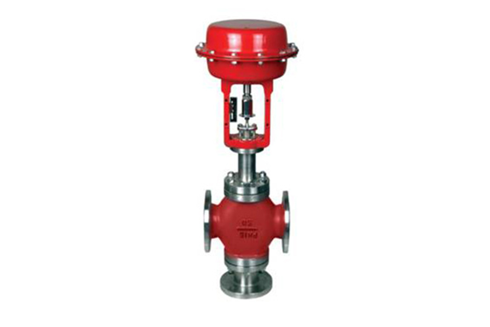
Structure and Principle
The cut-off valve is composed of a pneumatic diaphragm actuator and a valve body, connected by three columns or brackets in the middle. There are three forms of shut-off valves: single seat (P), sleeve (M), and three-way (N).The actuator has two forms: positive and negative. When the signal pressure input is 0.2Mpa, the push rod extends out of the diaphragm chamber (moves downward), which is called positive action, and cooperates with the valve to form an air tight type. When the signal pressure input is 0.2Mpa, the push rod retreats into the membrane chamber (moves upward), which is called a reaction and cooperates with the valve to form an air opening. Three way valve, due to the simultaneous presence of opening and closing inside the valve, there is no distinction between gas opening and gas closing. Its principle: When the signal pressure is 0, due to the pre tension force of the spring, the valve core is in its initial state, normally open or normally closed. When the signal pressure is input at 0.2Mpa, it acts on the diaphragm to generate thrust, compress the spring, drive the push rod and valve stem, and move the valve core to the limit position, achieving full valve closure (full open) or changing the flow direction of the medium. When the signal pressure input is "0", the force acting on the diaphragm disappears, and due to the reaction force of the spring, the valve core returns to its initial state.
Model preparation instructions
There are three main types of ZMQ type shut-off valves in our factory:1. ZMQP: Pneumatic diaphragm single seat cut-off valve, such as ZMQP-16K: Pneumatic open type, the valve is normally closed when the actuator has no air source. B: Pneumatic closed type, the valve is normally open when the actuator has no air source. Z: Type of actuator; M: Membrane type; Q: Cut off valve; P: Valve core type, single seat; 16: Nominal pressure, PN1.6Mpa.
2. ZMQM: Pneumatic thin film sleeve shut-off valve, such as ZMQM-16K: K: Pneumatic open type; M: Valve core type, sleeve; B: Airtight type
3. ZMAQ16-3: Pneumatic diaphragm three-way shut-off valve; A: Positive effect
Main Technical Parameters and Performance Indicators
| Nominal Diameter DN (mm) | 15 | 20 | 25 | 32 | 40 | 50 | 65 | 80 | 100 | 125 | 150 | 200 | |
| Rated Flow Coefficient (Kv) | Single Seat | 5 | 7 | 11 | 20 | 30 | 48 | 75 | 120 | 190 | 300 | 480 | 760 |
| Sleeve |
|
|
11 | 20 | 30 | 48 | 75 | 120 | 190 | 300 | 480 | 760 | |
| Rated Stroke (mm) | 8 | 12 | 20 | 25 | 40 | 50 | |||||||
| Effective Diaphragm Area (cm²) | 100 | 200 | 400 | 600 | 1000 | ||||||||
| Permissible Leakage | Single Seat Hard Seal *ml/min | 0 | 0 | 0 | 0 | 0 | 0 | 0.5 | 1.0 | 2.0 | 3.0 | 5.0 | |
| 15 | 20 | 50 | 80 | ||||||||||
| Soft Seal | Single Seat Class VI (tested with gas), 0 leakage (tested with water) according to GB/T4213 - 92 | ||||||||||||
| Operating Temperature (°C) | Soft Seal: -40 to 200; Hard Seal: -60 to 450 | ||||||||||||
| Nominal Pressure PN (MPa) | 1.6, 2.5, 4.0, 6.4 | ||||||||||||
| Switching Time | 0.5 - 5 seconds | ||||||||||||
| Permissible Pressure Difference (MPa) | Direct Acting | 6.4 | 4.2 | 2.5 | 1.7 | 1.6 | 0.85 | 1.8 | 1.2 | 0.85 | 0.65 | 0.84 | 0.53 |
| Reverse Acting | 6.4 | 6.0 | 3.4 | 2.3 | 2.8 | 1.1 | 1.4 | 1.5 | 0.90 | 0.65 | 0.84 | 0.53 | |
| ZMQM Type | 6.4 | 4.0 | 3.0 | ||||||||||
| Signal Pressure (MPa) | 0.2. If higher than this value, an air filter regulator should be added in front. | ||||||||||||
1. The permissible pressure difference refers to the data configured with standard actuators. If users need to increase the permissible pressure difference, our factory can meet the users' needs by changing the actuator or spring.
2. For the shut-off valves with DN250 - 350, our factory designs them specifically according to the users' process parameters.
3. For the single - seat hard - seal leakage data, the first row is the water test, △P = △PMAX; the second row is the gas test, △P = 0.35MPa.
4. Please specify separately if stricter leakage requirements are needed.
Main Component Materials
| Component Name | Material |
| Valve Body | HT200, ZG230 - 450, ZG0Cr18Ni9Ti |
| Valve Plug and Valve Seat | 1Cr18Ni9Ti, 0Cr18Ni12Mo2Ti (surfaced with Stellite), PTFE |
| Valve Stem | 1Cr18Ni9Ti, 2Cr13 |
| Sealing Sleeve | HT200, ZG230 - 450, Q235A, 1Cr18Ni9Ti |
| Diaphragm | Nitrile, Ethylene - Propylene, Fluorine, Oil - resistant Rubber |
| Diaphragm Cover | Q235, Q235 coated with PTFE |
| Packing | Polytetrafluoroethylene, Flexible Graphite |
| Spring | 60Si2Mn |
| Gasket | Xb350, Graphite - Clad Metal |
External Dimensions and Weight
| Nominal Diameter (DN) | L | ΦA | H0 | H1 | H2 | H3 | Weight Kg | Signal Connector Thread | |
| Pn16, 25, 40 | PN64 | ||||||||
| 15 | 130 | 210 | 196 | 120 | 240 | 305 | 345 | 10 | M10×1 |
| 20 | 150 | 230 | 196 | 120 | 295 | 340 | 415 | 10 | |
| 25 | 160 | 230 | 196 | 130 | 298 | 345 | 428 | 12 | |
| 32 | 180 | 260 | 196 | 140 | 308 | 370 | 448 | 15 | |
| 40 | 200 | 260 | 232 | 140 | 308 | 380 | 448 | 19 | |
| 50 | 230 | 300 | 232 | 153 | 315 | 390 | 468 | 23 | |
| 65 | 290 | 340 | 308 | 178 | 383 | 475 | 561 | 35 | |
| 80 | 310 | 380 | 308 | 190 | 388 | 490 | 578 | 56 | |
| 100 | 350 | 430 | 308 | 201 | 389 | 500 | 590 | 70 | |
| 125 | 400 | 500 | 394 | 266 | 626 | 765 | 886 | 105 | M16×1.5 |
| 150 | 480 | 550 | 498 | 320 | 688 | 825 | 1008 | 145 | |
| 200 | 600 | 650 | 498 | 361 | 759 | 927 | 1120 | 205 | |
When equipped with a simple handwheel: for DN15 - DN50, the total height increases by 90; for DN65 - DN100, the total height increases by 125; for DN100 - DN200, the total height increases by 225. The weight is based on PN16 as an example.
Connection Dimensions and Standards
• Flanges are in accordance with GB/T9113 - 2000 (default standard), and can also be in accordance with JB/T79.1 - 94, JB/T79.2 - 94, or HG20592 - HG20635 - 97.
• Flange sealing surface type: Convex - faced flange for PN16; Convex - faced flange for PN25; Male - and - female faced flange for PN40, PN64 (63), with the valve body being the female - faced flange.
• Flange end - to - end distance is in accordance with GB12221 - 89 (other standards must be specified).
• Welding connection groove is in accordance with GB12224 - 89.
• Actuator air signal interface: Internal thread M10×1 (DN ≤ 100), internal thread M16×1.5 (DN > 100).
• The valve body flange and flange end - to - end distance can be manufactured according to the standards specified by users, such as ANSI, JIS, DIN, etc.
Available Accessories
Handwheel, Simple Handwheel, Solenoid Valve, Travel Switch (Contact Position Indicator), Air Filter Regulator, Diaphragm, Flange
(1) Before installation, check that the product model, tag number, and specifications match the requirements. Inspect the entire valve for missing or loose parts.
(2) Prior to installation, clean the pipeline. Ensure there is sufficient straight pipe section at the valve inlet and install a filter. When connecting the valve body to the pipeline flanges, ensure coaxiality.
(3) Thoroughly clean the pipeline before installing the valve.
(4) The installation site should ensure the safety of personnel and equipment, facilitating operation, disassembly, and maintenance.
(5) The valve should be installed vertically upright on horizontal pipelines. If necessary, it can be installed at an angle, but horizontal installation should be avoided. For occasions with heavy valve weight or vibration, use a support frame.
(6) The medium flow direction must align with the arrow on the valve body. The air supply should be dry and oil-free. The valve should be used in environments with temperatures ranging from -20℃ to 55℃.
(1) Cleaning the Valve: For general media, cleaning with water is sufficient. For media harmful to health, first understand their properties and then select an appropriate cleaning method.
(2) Disassembly: Remove rust from exposed rusted parts first. Before derusting, protect the machined surfaces of precision parts such as the valve seat, valve plug, valve stem, and push rod. Use special tools when disassembling the valve seat.
(3) Valve Seat: Minor rust or wear on the sealing surface can be repaired by machining. If damage is severe, replace the seat. However, both repaired and replaced hard sealing surfaces must be lapped.
(4) Valve Stem: If the surface is damaged, it must be replaced.
(5) Damage to Push Rod, Guide, and Sealing Surfaces: Reverse-acting actuators must be replaced; direct-acting actuators can be reused after proper repair.
(6) Compression Spring: If there are cracks or other defects affecting strength, replace it immediately.
(7) Wear Parts: Packing, gaskets, and O-rings must be replaced entirely during each maintenance. Check the valve plug and diaphragm for cracks, aging, or corrosion that may cause future failures. Decide whether to replace them based on inspection results, but the diaphragm service life should not exceed 2-3 years.
(8) When reassembling the valve, ensure alignment. Tighten bolts diagonally and lubricate sliding parts. After reassembly, debug the valve according to the factory test items and methods. During this period, accurately adjust the packing compression force and the valve plug closing position.
-
If the model has not been selected before ordering, please provide us with the operating parameters:
(1) Nominal diameter DN (mm);
(2) Nominal pressure (MPa or bar);
(3) Fluid properties (including medium temperature, viscosity, or acidity/alkalinity);
(4) Pressure before and after the valve (pressure differential);
(5) Requirements for flow characteristics;
(6) Materials of valve body and valve core;
(7) Connection type;
(8) Driving method (provide air supply pressure, driving voltage);
(9) Supporting accessories (for pneumatic valves, it is recommended that users install an air filter triplet and a 2-position 5-way solenoid valve);
(10) On-site working conditions. -
If the product model of our company has been selected by the design unit, please order directly from our production department according to the model;
-
When the application occasion is very important or the pipeline is relatively complex, please provide the design drawings and detailed parameters as much as possible, and our experts will review and check them for you.


