


Introduction
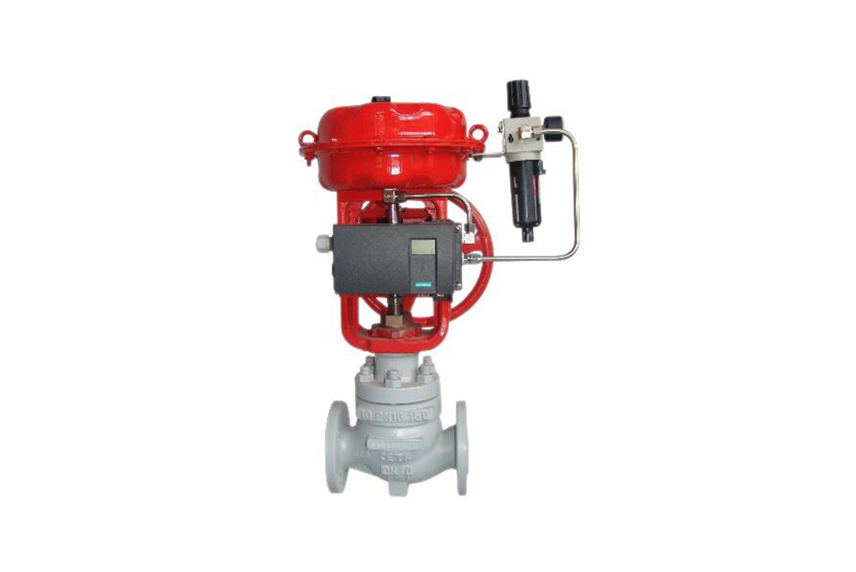
The pneumatic flow control valve adopts a sleeve-guided balanced valve trim and a split-type valve cage combination. It can be optionally equipped with an ordinary double-seat or single-sealed valve seat with a movable sealing ring. The labyrinth-type multi-layer gasket valve cage structure can effectively reduce noise, achieve multi-stage pressure reduction and prevent cavitation damage. It has strong anti-cavitation ability, is suitable for heavy loads, especially for the control of high-differential-pressure fluids, and can be used in very harsh working conditions.
Technical Parameter
Main technical parameters
| Nominal dimeter | mm | 20 | 25 | 32 | 40 | 50 | 65 | 80 | 100 | 125 | 150 | 200 | 250 | 300 |
|---|---|---|---|---|---|---|---|---|---|---|---|---|---|---|
| inch | 3/4〞 | 1〞 | 1.25〞 | 1.5〞 | 2〞 | 2.5〞 | 3〞 | 4〞 | 5〞 | 6〞 | 8〞 | 10〞 | 12〞 | |
| Travel distance (mm) | 16 | 25 | 40 | 60 | 100 | |||||||||
| Pressure rating | ANSI class 150 300 600; JIS 10k 20k 30k 40k; PN 1.6 4.0 6.4 10.0Mpa | |||||||||||||
| Valve core shape | Balanced labyrinth gasket valve cage | |||||||||||||
| Traffic characteristics | Improvement percentage, straight line | |||||||||||||
| Rangeability | 50:1 | |||||||||||||
| Connection type | Flange style | Flange style | ||||||||||||
| Welded type | welded type | |||||||||||||
| External dimensions | Please refer to the external dimensions | |||||||||||||
| Upper valve cover form | Standard type: -5℃~230℃ | |||||||||||||
| Heat dissipation type: -45 ℃~5 ℃ or above 230 ℃ | ||||||||||||||
| Extended type: -196 ℃~-45 ℃ | ||||||||||||||
| Bellows sealed type (formal or welded), steam jacket type | ||||||||||||||
| For the matching and working temperature range of valve body and internal component materials, please refer to the matching and working temperature range of component materials | ||||||||||||||
| Filler | PTFE V-shaped packing, PTFE carbon fiber, PTFE asbestos, and flexible graphite | |||||||||||||
| Grommet | Serrated washer (extremely soft carbon steel, SUS316, other alloy steels) | |||||||||||||
| Leakage | The metal valve seat meets the standard ANSI 16.104 Grade III, with a CV value less than 0.1% of the rated CV value | |||||||||||||
| The PTFE valve seat meets the standard ANSI 16.104 Grade IV and is less than 0.01% of the rated CV value. Please refer to the leakage rate | ||||||||||||||
| Maximum allowable pressure difference | Please refer to the maximum allowable pressure difference | |||||||||||||
| Actuator | Pneumatic please refer to pneumatic actuator, electric please refer to electric actuator | |||||||||||||
Main parts
| Serial Number | Part | Material | ||
|---|---|---|---|---|
| 1 | Valve body | WCB | CF8M | CF8 |
| 2 | Valve cover | WCB | CF8M | CF8 |
| 3 | Sleeve | 304 | 316 | 304 |
| 4 | Valve core | 304 | 316 | 304 |
| 5 | Sealing shaft sleeve | 304 | 316 | 304 |
| 6 | Valve stem | 304 | 316 | 304 |
| 7 | Filler | PTFE or flexible graphite | ||
| 8 | Packing bushing | 304 | 316 | 304 |
| 9 | Balance sealing ring | H461# | ||
| 10 | O-ring seal | NBR or FKM | ||
| 11 | Dust sealing ring | NBR or FKM | ||
| 12 | Packing seat | 304 | 316 | 304 |
| 13 | Grommet | 304 or 316+flexible graphite | ||
| 14 | Cover bolt | 35# | 316 | 304 |
| 15 | Gland nut | 35# | 316 | 304 |
| 16 | Stem nut | 304 | 304 | 304 |
Flow coefficient CV value
| Nominal diameter | mm | 25 | 32 | 40 | 50 | 65 | 80 | 100 | 125 | 150 | 200 | 250 | 300 | ||||||||||
|---|---|---|---|---|---|---|---|---|---|---|---|---|---|---|---|---|---|---|---|---|---|---|---|
| inch | 1〞 | 1.25〞 | 1.5〞 | 2〞 | 2.5〞 | 3〞 | 4〞 | 5〞 | 6〞 | 8〞 | 10〞 | 12〞 | |||||||||||
| Valve core size (mm) | 25 | 32 | 40 | 50 | 65 | 80 | 100 | 125 | 150 | 200 | 250 | 300 | |||||||||||
| Rated CV value | Equal percentage | 10 | 17 | 24 | 44 | 68 | 99 | 175 | 275 | 360 | 640 | 1000 | 1450 | ||||||||||
| linearity | 13 | 18 | 32 | 51 | 80 | 205 | 115 | 320 | 513 | 805 | 1200 | 1600 | |||||||||||
| Porous type | 5.8 | 9.6 | 16 | 40.2 | 51 | 70 | 138 | 177 | 256 | 464 | 761 | 1090 | |||||||||||
| level 2 | 4.7 | 7.1 | 10.8 | 18.3 | 29.2 | 49 | 85 | 104 | 143 | 224 | 410 | 492 | |||||||||||
| level 4 | 3.8 | 5.8 | 8.3 | 15.2 | 24.3 | 40.5 | 68 | 83 | 114 | 180 | 326 | 367 | |||||||||||
| level 6 | 3.2 | 4.8 | 6.7 | 12.2 | 19.6 | 33 | 58 | 70 | 94 | 142 | 273 | 290 | |||||||||||
| level 8 | 2.4 | 3.4 | 4.6 | 9.2 | 14.5 | 23.9 | 43 | 54 | 75 | 109 | 214 | 238 | |||||||||||
External dimensions of the actuator
| Valve Dimension | L | p | A | Standard type | Heat dissipation type | Elongate type | Connection size of actuator | |||||||||
|---|---|---|---|---|---|---|---|---|---|---|---|---|---|---|---|---|
| PN1.6 | PN4.0 | PN6.4 | h1 | H1 | h1 | H1 | H1 | B | H3 | M | D | d1 | z-d | |||
| h1=800 | ||||||||||||||||
| 3/4" | 184 | 194 | 206 | 52 | 285 | 132 | 482 | 282 | 632 | 1226 | 290 | 105 | M12*1.25 | 60 | 80 | 4-10 |
| 1" | 184 | 197 | 210 | 52 | 285 | 132 | 482 | 282 | 632 | 12 26 | 290 | 105 | M12*1.25 | 60 | 80 | 4-10 |
| 1.5" | 222 | 235 | 251 | 68 | 285 | 179 | 529 | 349 | 699 | 1246 | 370 | 105 | M12*1.25 | 60 | 80 | 410 |
| 360 | 615 | 785 | 1330 | 370 | 135 | M16*1.5 | 80 | 105 | 4-12 | |||||||
| 2.5" | 276 | 292 | 311 | 93 | 360 | 214 | 650 | 414 | 850 | 1367 | 410 | 135 | M16*1.5 | 80 | 105 | 4-12 |
| 470 | 802 | 1002 | 1519 | 410 | 160 | M20*1.5 | 95 | 118 | 4-14 | |||||||
| 3" | 298 | 317 | 337 | 98 | 360 | 221 | 657 | 421 | 857 | 1367 | 440 | 135 | M16*1.5 | 80 | 105 | 4-12 |
| 470 | 809 | 1009 | 1519 | 440 | 160 | M20*1.5 | 95 | 118 | 4-14 | |||||||
| 4" | 352 | 368 | 394 | 117 | 360 | 234 | 670 | 434 | 870 | 1367 | 490 | 135 | M16*1.5 | 80 | 105 | 4-12 |
| 470 | 822 | 1002 | 1519 | 490 | 160 | M20*1.5 | 95 | 118 | 4-14 | |||||||
| 5" | 403 | 425 | 460 | 133 | 470 | 270 | 858 | 527 | 1115 | 1536 | 560 | 160 | M20*1.5 | 95 | 118 | 4-14 |
| 6" | 451 | 473 | 508 | 150 | 470 | 294 | 882 | 554 | 1142 | 1536 | 630 | 160 | M20*1.5 | 95 | 118 | 4-14 |
| 8" | 543 | 568 | 610 | 186 | 470 | 331 | 919 | 591 | 1179 | 1536 | 760 | 160 | M20*1.5 | 95 | 118 | 4-14 |
| 10" | 673 | 700 | 770 | 245 | 580 | 387 | 1054 | 637 | 1305 | - | - | 178 | M20*1.5 | 100 | 130 | 4-18 |
| 12" | 737 | 775 | 819 | 248 | 580 | 465 | 1132 | 715 | 1382 | - | - | 178 | M20*1.5 | 100 | 130 | 4-18 |
External dimensions of the actuator
| Valve Dimension | PN1.6/4.0 | L3 | Standard type | Heat dissipation type | Elongate type | A | Connection size of actuator | ||||||||||
|---|---|---|---|---|---|---|---|---|---|---|---|---|---|---|---|---|---|
| PN1.6 | PN4.0 | PN6.4 | h1 | H1 | h1 | H1 | H1 | B | H3 | M | D | d1 | z-d | ||||
| L1 | L2 | h1=800 | |||||||||||||||
| 3/4" | 75 | 75 | - | - | - | - | - | - | - | 1301 | 290 | 285 | 105 | M12*1.25 | 60 | 80 | 4-10 |
| 1" | 75 | 75 | - | - | - | - | - | - | - | 1301 | 290 | 285 | 105 | M12*1.25 | 60 | 80 | 4-10 |
| 1.5" | 85 | 85 | 111 | 117 | 125 | 149 | 616 | 319 | 786 | 1329 | 335 | 360 | 135 | M12*1.25 | 60 | 80 | 4-10 |
| 702 | 872 | 1415 | 370 | 285 | 105 | M16*1.5 | 80 | 105 | 4-12 | ||||||||
| 2" | 110 | 110 | 127 | 133 | 143 | 159 | 639 | 326 | 809 | 1354 | 370 | 285 | 105 | M12*1.25 | 60 | 80 | 4-10 |
| 725 | 895 | 1440 | 370 | 360 | 135 | M16*1.5 | 80 | 105 | 4-12 | ||||||||
| 2.5" | 140 | 140 | 138 | 146 | 156 | 188 | 780 | 388 | 980 | 1517 | 410 | 360 | 135 | M16*1.5 | 80 | 105 | 4-12 |
| 922 | 1122 | 1669 | 410 | 470 | 160 | M20*1.5 | 95 | 118 | 4-14 | ||||||||
| 3" | 160 | 150 | 149 | 159 | 168 | 194 | 789 | 394 | 898 | 1517 | 440 | 360 | 135 | M16*1.5 | 80 | 105 | 4-12 |
| 941 | 1141 | 1669 | 440 | 470 | 160 | M20*1.5 | 95 | 118 | 4-14 | ||||||||
| 4" | 170 | 160 | 176 | 184 | 197 | 234 | 854 | 413 | 1033 | 1517 | 560 | 360 | 135 | M16*1.5 | 80 | 105 | 4-12 |
| 1006 | 1185 | 1669 | 560 | 470 | 160 | M20*1.5 | 95 | 118 | 414 | ||||||||
| 5" | - | - | 200 | - | - | 270 | 1047 | 527 | 1307 | 1615 | 560 | 470 | 160 | M20*1.5 | 95 | 118 | 4-14 |
| 6" | - | - | 240 | - | - | 294 | 1071 | 554 | 1334 | 1615 | 630 | 470 | 160 | M20*1.5 | 95 | 118 | 4-14 |
| 8" | - | - | 300 | - | - | 331 | 1108 | 591 | 1371 | 1615 | 760 | 470 | 160 | M20*1.5 | 95 | 118 | 4-14 |
Valve Installation & Maintenance
Valve Installation:
(1) Before installation, check that the product model, tag number, and specifications match the requirements. Inspect the entire valve for missing or loose parts.
(2) Prior to installation, clean the pipeline. Ensure there is sufficient straight pipe section at the valve inlet and install a filter. When connecting the valve body to the pipeline flanges, ensure coaxiality.
(3) Thoroughly clean the pipeline before installing the valve.
(4) The installation site should ensure the safety of personnel and equipment, facilitating operation, disassembly, and maintenance.
(5) The valve should be installed vertically upright on horizontal pipelines. If necessary, it can be installed at an angle, but horizontal installation should be avoided. For occasions with heavy valve weight or vibration, use a support frame.
(6) The medium flow direction must align with the arrow on the valve body. The air supply should be dry and oil-free. The valve should be used in environments with temperatures ranging from -20℃ to 55℃.
Valve Maintenance:
(1) Cleaning the Valve: For general media, cleaning with water is sufficient. For media harmful to health, first understand their properties and then select an appropriate cleaning method.
(2) Disassembly: Remove rust from exposed rusted parts first. Before derusting, protect the machined surfaces of precision parts such as the valve seat, valve plug, valve stem, and push rod. Use special tools when disassembling the valve seat.
(3) Valve Seat: Minor rust or wear on the sealing surface can be repaired by machining. If damage is severe, replace the seat. However, both repaired and replaced hard sealing surfaces must be lapped.
(4) Valve Stem: If the surface is damaged, it must be replaced.
(5) Damage to Push Rod, Guide, and Sealing Surfaces: Reverse-acting actuators must be replaced; direct-acting actuators can be reused after proper repair.
(6) Compression Spring: If there are cracks or other defects affecting strength, replace it immediately.
(7) Wear Parts: Packing, gaskets, and O-rings must be replaced entirely during each maintenance. Check the valve plug and diaphragm for cracks, aging, or corrosion that may cause future failures. Decide whether to replace them based on inspection results, but the diaphragm service life should not exceed 2-3 years.
(8) When reassembling the valve, ensure alignment. Tighten bolts diagonally and lubricate sliding parts. After reassembly, debug the valve according to the factory test items and methods. During this period, accurately adjust the packing compression force and the valve plug closing position.
Ordering Instructions
When placing an order, please fill in the Specification Sheet or specify the following information:
-
If the model has not been selected before ordering, please provide us with the operating parameters:
(1) Nominal diameter DN (mm);
(2) Nominal pressure (MPa or bar);
(3) Fluid properties (including medium temperature, viscosity, or acidity/alkalinity);
(4) Pressure before and after the valve (pressure differential);
(5) Requirements for flow characteristics;
(6) Materials of valve body and valve core;
(7) Connection type;
(8) Driving method (provide air supply pressure, driving voltage);
(9) Supporting accessories (for pneumatic valves, it is recommended that users install an air filter triplet and a 2-position 5-way solenoid valve);
(10) On-site working conditions. -
If the product model of our company has been selected by the design unit, please order directly from our production department according to the model;
-
When the application occasion is very important or the pipeline is relatively complex, please provide the design drawings and detailed parameters as much as possible, and our experts will review and check them for you.


