


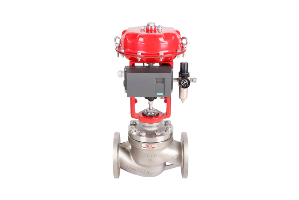
The ZJHP pneumatic diaphragm single-seat control valve consists of a pneumatic multi-spring diaphragm actuator and a low-flow-resistance single-seat valve. The new-type actuator is low in height, light in weight, and easy to install and calibrate. The new-type valve body is compact in structure, with smooth flow paths and a large flow coefficient.
The pneumatic diaphragm single-seat control valve operates stably, with reliable action characteristics, precise flow characteristics, and a large adjustable range. High-quality control effects have been achieved in a wide range of applications.
Pneumatic diaphragm single-seated control valve Technical parameters and performance:
Valve body part:
| Valve body type: | Straight-through cast spherical valve |
|---|---|
| Nominal diameter: | DN20, 25, 32, 40, 50, 65, 80, 100, 200 |
| Nominal pressure: | PN 1.6, 2.5, 4.0, 6.4, 10.0Mpa |
| ANSI 150, 300, 600Lb | |
| JIS 10K, 20K, 30K, 40K | |
| Connection method: | Flange: FF, RF, RTJ, etc. |
| Thread: (Suitable for below 1") | |
| Welding: SW, BW | |
| Flange distance: | Complies with IEC 534 |
| Bonnet type: | Standard type, extended type (heat dissipation, low temperature, bellows seal) |
| Packing: | V-type PTFE, flexible graphite packing, etc. |
| Gasket: | Metal-clad graphite gasket, PTFE gasket |
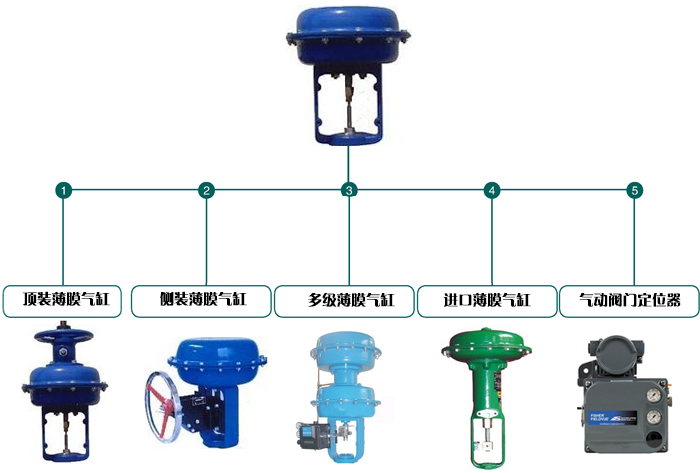
| Actuator: | Pneumatic: Multi-spring actuator, single-spring actuator |
| Electric: 3810L series, SL series |
Valve internal parts:
| Plug type: | Single-seated plunger |
|---|---|
| Flow characteristic: | Equal percentage, linear, quick opening |
| Internal parts material: | Refer to the appendix for the standard material combination and the applicable temperature and pressure range. |
User options available
| Valve body | Type | Straight-through | Bonnet | Type | Standard, extended type |
|---|---|---|---|---|---|
| Material | WCB, WC9, 304, 316, etc. | Material | WCB, WC9, 304, 316, etc. | ||
| Plug | Characteristic | Linear, equal percentage, quick opening | Packing | "V"-type PTFE, flexible graphite, bellows | |
| Material | 304, 304 + STL/PTFE, 316, 316 + STL/PTFE | ||||
| Actuator | Pneumatic: See Table 8 | ||||
| Electric: See Table 7 | |||||
| Positioner | Electro-pneumatic valve positioner, intelligent digital positioner | ||||
| Accessories | Solenoid valve, valve position feedback device, manual operator, position holding valve, air filter regulator, etc. | ||||
Materials and internal structure
The body material is carbon steel
| 1 | Valve body | WCB | LCB | WC9 |
|---|---|---|---|---|
| 2 | Gasket | 316 + graphite/PTEF | ||
| 3 | Bolt | 35 | 40MnB | 25Cr2Mo1VA |
| 4 | Seat | 304 | 304 | 304 |
| 5 | Plug (stem) | 304 | 304 | 304 |
| 6 | Gasket | 316 + graphite/PTEF | ||
| 7 | Guide sleeve | 304 | 304 | 304 |
| 8 | Bonnet | WCB | LCB | WC9 |
| 9 | Nut | 25 | 35 | 25Cr2Mo1VA |
| 10 | Packing gland | 304 | 304 | 304 |
| 11 | Packing | PTFE/flexible graphite | ||
| 12 | Compression sleeve nut | 304 | 304 | 304 |
The body material is stainless steel
| 1 | Valve body | CF8 | CF8M | CF3M |
|---|---|---|---|---|
| 2 | Gasket | 316 + graphite/PTEF | ||
| 3 | Bolt | 304 | 316 | 316L |
| 4 | Seat | 304 | 316 | 316L |
| 5 | Plug (stem) | 304 | 316 | 316L |
| 6 | Gasket | 316 + graphite/PTEF | ||
| 7 | Guide sleeve | 304 | 316 | 316L |
| 8 | Bonnet | CF8 | CF8M | CF3M |
| 9 | Nut | 304 | 316 | 316L |
| 10 | Packing gland | 304 | 316 | 316L |
| 11 | Packing | PTFE/flexible graphite | ||
| 12 | Compression sleeve nut | 304 | 316 | 316L |
Note:
1. The above is the standard configuration structure. The seat is metal-to-metal, and the PTFE soft seat is an optional part for Class VI sealing. Hardened valve internal parts with Stellite alloy coating can also be provided. For specific operating temperatures, we have more reasonable bolt and nut selections.
2. The PTFE V-ring valve stem packing is the standard configuration, and flexible graphite can also be selected. An extended bonnet equipped with graphite packing can be used in applications where the temperature exceeds 232°C (450°F).
3. The standard valve body materials are carbon steel and stainless steel. Various alloy materials for highly corrosive applications can also be provided.
Dimensions, reduced-port internal parts, and rated Cv values for stroke:
| Valve size inch(mm) | Plug size(mm) | Rated stroke(mm) | Rated Cv values | |||||||||
|---|---|---|---|---|---|---|---|---|---|---|---|---|
| Valve opening % stroke | ||||||||||||
| Equal percentage characteristic | Linear characteristic | |||||||||||
| 10% | 30% | 50% | 70% | 100% | 10% | 30% | 50% | 70% | 100% | |||
| 3/4 | 8 | 16 | 0.09 | 0.17 | 0.34 | 0.95 | 1.6 | 0.27 | 0.68 | 1.09 | 1.49 | 1.8 |
| -20 | 10 | 0.14 | 0.27 | 0.53 | 1.48 | 2.5 | 0.42 | 1.06 | 1.69 | 2.32 | 2.8 | |
|
|
15 | 0.22 | 0.43 | 0.85 | 2.37 | 4 | 0.67 | 1.66 | 2.65 | 3.65 | 4.4 | |
|
|
20 | 0.34 | 0.68 | 1.35 | 3.74 | 6.3 | 1.05 | 2.6 | 4.16 | 5.72 | 6.9 | |
| 1 | 15 | 16 | 0.22 | 0.43 | 0.85 | 2.37 | 4 | 0.67 | 1.66 | 2.56 | 3.65 | 4.4 |
| -25 | 20 | 0.34 | 0.68 | 1.35 | 3.74 | 6.3 | 1.05 | 2.6 | 4.16 | 5.72 | 6.9 | |
|
|
25 | 0.55 | 1.08 | 2.14 | 5.93 | 10 | 1.67 | 4.15 | 6.64 | 9.11 | 11 | |
| 1 1/4 | 20 | 25 | 0.34 | 0.68 | 1.35 | 3.74 | 6.3 | 1.05 | 2.6 | 4.16 | 5.72 | 6.9 |
| -32 | 25 | 0.55 | 1.08 | 2.14 | 5.93 | 10 | 1.67 | 4.15 | 6.64 | 9.11 | 11 | |
|
|
32 | 0.87 | 1.73 | 3.42 | 9.49 | 16 | 2.67 | 6.63 | 10.62 | 14.58 | 17.6 | |
| 1-1/2 | 25 | 25 | 0.55 | 1.08 | 2.14 | 5.93 | 10 | 1.67 | 4.15 | 6.64 | 9.11 | 11 |
| -40 | 32 | 0.87 | 1.73 | 3.42 | 9.49 | 16 | 2.67 | 6.63 | 10.62 | 14.58 | 17.6 | |
|
|
40 | 1.36 | 2.72 | 5.35 | 14.82 | 25 | 4.17 | 10.37 | 16.59 | 22.79 | 27.5 | |
| 2 | 32 | 25 | 0.87 | 1.73 | 3.42 | 9.49 | 16 | 2.67 | 6.63 | 10.62 | 14.58 | 17.6 |
| -50 | 40 | 1.36 | 2.72 | 5.35 | 14.82 | 25 | 4.17 | 10.37 | 16.59 | 22.79 | 27.5 | |
|
|
50 | 2.18 | 4.32 | 8.54 | 23.71 | 40 | 6.67 | 16.68 | 26.56 | 36.46 | 44 | |
| 2 1/2 | 40 | 40 | 1.36 | 2.72 | 5.35 | 14.82 | 25 | 4.17 | 10.37 | 16.59 | 22.79 | 27.5 |
| -65 | 50 | 2.18 | 4.32 | 8.54 | 23.71 | 40 | 6.67 | 16.58 | 26.56 | 36.46 | 44 | |
|
|
65 | 3.34 | 6.81 | 13.45 | 37.35 | 63 | 10.47 | 20.01 | 41.63 | 57.17 | 69 | |
| 3 | 50 | 40 | 2.18 | 4.32 | 8.54 | 23.71 | 40 | 6.67 | 16.58 | 26.56 | 36.46 | 44 |
| -80 | 65 | 3.34 | 6.81 | 13.45 | 37.35 | 63 | 10.47 | 26.01 | 41.63 | 57.17 | 69 | |
|
|
80 | 5.45 | 10.81 | 21.36 | 59.28 | 100 | 16.69 | 41.46 | 66.37 | 91.14 | 110 | |
| 4 | 65 | 40 | 3.34 | 6.81 | 13.45 | 37.35 | 63 | 10.47 | 26.01 | 41.63 | 57.17 | 69 |
| -100 | 80 | 5.45 | 10.81 | 21.36 | 59.28 | 100 | 16.69 | 41.46 | 66.37 | 91.14 | 110 | |
|
|
100 | 8.72 | 17.29 | 34.17 | 94.85 | 160 | 26.7 | 66.34 | 106.2 | 145.8 | 176 | |
| 5 | 80 | 60 | 13.62 | 10.81 | 21.36 | 59.28 | 100 | 16.69 | 41.46 | 66.37 | 91.14 | 110 |
| -125 | 100 | 21.8 | 17.29 | 34.17 | 94.85 | 160 | 26.7 | 66.34 | 106.2 | 145.8 | 176 | |
|
|
125 | 13.62 | 27.06 | 53.4 | 148.2 | 250 | 41.72 | 103.7 | 165.9 | 227.9 | 275 | |
| 6 | 100 | 60 | 21.8 | 17.29 | 34.17 | 94.85 | 160 | 26.7 | 66.34 | 106.2 | 145.8 | 176 |
| -150 | 125 | 13.62 | 27.06 | 53.4 | 148.2 | 250 | 41.72 | 103.7 | 165.9 | 227.9 | 275 | |
|
|
150 | 21.8 | 43.23 | 85.42 | 237.1 | 400 | 66.75 | 165.85 | 265.5 | 364.6 | 440 | |
| 8 | 125 | 60 | 13.62 | 27.06 | 53.4 | 148.2 | 250 | 71.72 | 103.7 | 165.9 | 227.9 | 275 |
| -200 | 150 | 21.8 | 43.23 | 85.42 | 237.1 | 400 | 66.75 | 165.85 | 265.5 | 364.6 | 440 | |
|
|
200 | 34.34 | 68.08 | 134.5 | 373.5 | 630 | 104.7 | 260.1 | 416.3 | 571.7 | 690 | |
Maximum allowable pressure difference:
Multi-spring diaphragm actuator Unit: Mpa
| Pneumatic actuator specification | Air supply pressure Kpa | Spring range Kpa | Plug size inch(mm) | ||||||||||
|---|---|---|---|---|---|---|---|---|---|---|---|---|---|
| 3/4 20 | 1 25 | 1 | 1 | 2 50 | 2 | 3 80 | 4 400 | 5 125 | 6 150 | 8 200 | |||
| ZHB22 | 140 | 20 - 100 | 1.17 | 0.75 | - | - | - | - | - | - | - | - | - |
| 240 | 40 - 200 | 2.73 | 1.75 | - | - | - | - | - | - | - | - | - | |
| 300 | 80 - 240 | 5.85 | 3.75 | - | - | - | - | - | - | - | - | - | |
| ZHB23 | 140 | 20 - 100 | 1.64 | 1.05 | 0.63 | 0.4 | 0.26 | - | - | - | - | - | - |
| 240 | 40 - 200 | 3.82 | 2.45 | 1.49 | 0.96 | 0.61 | - | - | - | - | - | - | |
| 300 | 80 - 240 | 8.19 | 5.24 | 3.19 | 2.05 | 1.31 | - | - | - | - | - | - | |
| ZHB34 | 140 | 20 - 100 | - | - | 1.02 | 0.66 | 0.42 | 0.24 | 0.16 | 0.1 | - | - | - |
| 240 | 40~200 | - | - | 2.38 | 1.53 | 0.98 | 0.58 | 0.38 | 0.24 | - | - | - | |
| 300 | 80~240 | - | - | 5.12 | 3.28 | 2.1 | 1.24 | 0.82 | 0.52 | - | - | - | |
| ZHB45 | 140 | 20~100 | - | - | - | - | - | 0.4 | 0.26 | 0.17 | 0.11 | 0.07 | 0.02 |
| 240 | 40~200 | - | - | - | - | - | 0.93 | 0.61 | 0.39 | 0.25 | 0.17 | 0.07 | |
| 300 | 80~240 | - | - | - | - | - | 1.98 | 1.32 | 0.84 | 0.54 | 0.37 | 0.16 | |
※The above recommendations for using pressure differentials are only relative. There are multiple configuration combinations for various pressure differentials. For complex control systems, please contact our technical department. We have many years of experience in process control product production and can provide you with more reasonable actuator configurations.
Configure ZH series pneumatic actuator control valve with external dimensions in mm
| Valve Dimension | L | H1 | H2 | h1 | H3 | C | B | A | L2 | 执行机构 | ||||||
|---|---|---|---|---|---|---|---|---|---|---|---|---|---|---|---|---|
| inch | mm | ANSI150 N16、25 | ANSI300 N40 | ANSI600PN64、100 | ||||||||||||
| 3/4 | 20 | 184 | 7.25 | 184 | 7.25 | 206 | 8.12 | 425 | 53 | 213 | 704 | 288 | 200 | 200 | 289 | ZHB-22 |
| 1 | 25 | 184 | 7.25 | 184 | 7.25 | 210 | 8.25 | 435 | 58 | 218 | 710 | 288 | 200 | 200 | 289 | ZHB-22 |
| 1 1/4 | 32 | 200 | 7.87 | 200 | 7.87 | 251 | 9.88 | 448 | 70 | 231 | 722 | 288 | 200 | 200 | 289 | ZHB-22 |
| 1 1/2 | 40 | 222 | 8.75 | 222 | 8.75 | 251 | 9.88 | 448 | 75 | 231 | 722 | 288 | 200 | 200 | 289 | ZHB-23 |
| 2 | 50 | 254 | 10 | 254 | 10 | 286 | 11.25 | 487 | 83 | 255 | 740 | 288 | 200 | 200 | 289 | ZHB-23 |
| 2 1/2 | 65 | 276 | 10.88 | 276 | 10.88 | 311 | 12.25 | 628 | 93 | 311 | 884 | 360 | 355 | 355 | 347 | ZHB-34 |
| 3 | 80 | 298 | 11.75 | 317 | 12.5 | 337 | 13.25 | 645 | 98 | 328 | 902 | 360 | 355 | 355 | 347 | ZHB-34 |
| 4 | 100 | 352 | 13.88 | 368 | 14.5 | 394 | 15.5 | 656 | 115 | 328 | 913 | 360 | 355 | 355 | 347 | ZHB-34 |
| 5 | 125 | 420 | 16.53 | 400 | 15.75 | 500 | 19.69 | 806 | 125 | 389 | 1274 | 470 | 570 | 570 | 476 | ZHB-45 |
| 6 | 150 | 451 | 17.75 | 473 | 18.62 | 508 | 20 | 857 | 143 | 440 | 1325 | 470 | 570 | 570 | 476 | ZHB-45 |
(1) Before installation, check that the product model, tag number, and specifications match the requirements. Inspect the entire valve for missing or loose parts.
(2) Prior to installation, clean the pipeline. Ensure there is sufficient straight pipe section at the valve inlet and install a filter. When connecting the valve body to the pipeline flanges, ensure coaxiality.
(3) Thoroughly clean the pipeline before installing the valve.
(4) The installation site should ensure the safety of personnel and equipment, facilitating operation, disassembly, and maintenance.
(5) The valve should be installed vertically upright on horizontal pipelines. If necessary, it can be installed at an angle, but horizontal installation should be avoided. For occasions with heavy valve weight or vibration, use a support frame.
(6) The medium flow direction must align with the arrow on the valve body. The air supply should be dry and oil-free. The valve should be used in environments with temperatures ranging from -20℃ to 55℃.
(1) Cleaning the Valve: For general media, cleaning with water is sufficient. For media harmful to health, first understand their properties and then select an appropriate cleaning method.
(2) Disassembly: Remove rust from exposed rusted parts first. Before derusting, protect the machined surfaces of precision parts such as the valve seat, valve plug, valve stem, and push rod. Use special tools when disassembling the valve seat.
(3) Valve Seat: Minor rust or wear on the sealing surface can be repaired by machining. If damage is severe, replace the seat. However, both repaired and replaced hard sealing surfaces must be lapped.
(4) Valve Stem: If the surface is damaged, it must be replaced.
(5) Damage to Push Rod, Guide, and Sealing Surfaces: Reverse-acting actuators must be replaced; direct-acting actuators can be reused after proper repair.
(6) Compression Spring: If there are cracks or other defects affecting strength, replace it immediately.
(7) Wear Parts: Packing, gaskets, and O-rings must be replaced entirely during each maintenance. Check the valve plug and diaphragm for cracks, aging, or corrosion that may cause future failures. Decide whether to replace them based on inspection results, but the diaphragm service life should not exceed 2-3 years.
(8) When reassembling the valve, ensure alignment. Tighten bolts diagonally and lubricate sliding parts. After reassembly, debug the valve according to the factory test items and methods. During this period, accurately adjust the packing compression force and the valve plug closing position.
-
If the model has not been selected before ordering, please provide us with the operating parameters:
(1) Nominal diameter DN (mm);
(2) Nominal pressure (MPa or bar);
(3) Fluid properties (including medium temperature, viscosity, or acidity/alkalinity);
(4) Pressure before and after the valve (pressure differential);
(5) Requirements for flow characteristics;
(6) Materials of valve body and valve core;
(7) Connection type;
(8) Driving method (provide air supply pressure, driving voltage);
(9) Supporting accessories (for pneumatic valves, it is recommended that users install an air filter triplet and a 2-position 5-way solenoid valve);
(10) On-site working conditions. -
If the product model of our company has been selected by the design unit, please order directly from our production department according to the model;
-
When the application occasion is very important or the pipeline is relatively complex, please provide the design drawings and detailed parameters as much as possible, and our experts will review and check them for you.


