


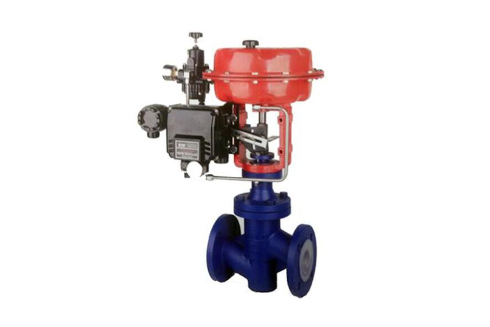
1. The pneumatic fluorine-lined single-seat control valve is an executive unit of instruments in automatic control systems. It adopts an electro-pneumatic valve positioner and is powered by electrical signals and compressed air. It receives 0-10mA •DC or 4-20mA •DC current signals input by the control system. The regulator converts the compressed air into a gas source pressure signal for input, and uses the thrust of the straight-stroke output to change the valve opening displacement, so as to achieve precise regulation and control of the process parameters of the fluid medium.
2. Pneumatic fluorine-lined single-seat control valves can be divided by action mode:
Direct action: Air-closed - normally open type (the valve position moves downward when the signal pressure increases), 《Type B》
Reverse action: Air-open - normally closed type (the valve position moves upward when the signal pressure increases), 《Type K》
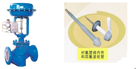
3. The fluorine-lined single-seat control valve is a straight-through single-seat cast spherical valve with a single-seat plunger-type valve core. All internal components of the valve, such as the valve body cavity, valve core, valve seat, and valve stem, are lined with 2.5-3mm thick perfluoroethylene-propylene (F46) plastic, which is resistant to strongly corrosive media such as acids and alkalis. It adopts a dual sealing system of polytetrafluoroethylene bellows and polytetrafluoroethylene packing. The bellows isolates the medium from the outside world to ensure flexible movement of the valve core up and down. It has excellent sealing performance. In case the bellows is damaged, the stuffing box can act as a second protective seal to ensure no leakage. The valve core and valve seat, fully lined with perfluoroethylene-propylene, form a soft seal, with a leakage rate lower than Grade IV standard. It is suitable for occasions where the pressure difference between the front and rear of the valve is small, and there are strict requirements on medium leakage and regulation accuracy.
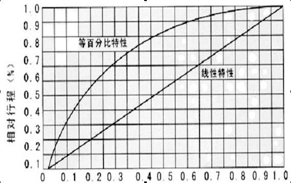
4. Different flow characteristics (equal percentage (logarithmic) and linear) can be obtained by changing the design of the valve core shape.
This series of products are widely used in automatic regulation and remote control of industrial production processes in chemical industry, petroleum, metallurgy, power stations, light industry and textile, papermaking, pharmacy and other fields. There are standard types and bellows-sealed types available. The pressure ratings of the products include PN1.0 and 1.6 MPa; the nominal diameters range from DN15 to 150mm; the minimum valve core diameter is DN10mm. The applicable fluid temperature is -20~+150℃; the valve bodies with DN20~32mm are split-type, and those with DN40~150mm are integral-type.
Main technical parameters:
| Model |
ZHA-22 ZHB-22 |
ZHA-23 ZHB-23 |
ZHB-34 ZHB-34 |
ZHA-45 ZHB-45 |
ZHA-56 ZHB-56 |
|---|---|---|---|---|---|
|
Effective area (c㎡) |
350 |
350 |
560 |
900 |
1600 |
|
Travel distance (mm) |
16 |
25 |
40 |
60 |
100 |
|
Spring range (KPa) |
20~100 (Standard): 40~200;80~240; 20~60; 60~100 |
||||
|
Operating mode |
Ordinary type, with manual handwheel operation type (side mounted, top mounted) |
||||
Electric pneumatic valve positioner:
Electric valve positioner is the main supporting instrument for pneumatic actuators in industrial automation. It can be used to improve the linearity of valve position, overcome the friction force of valve stem, and eliminate the influence of unbalanced force of regulating valve, so as to ensure that the valve position is proportional to the current signal of 0-10mA DC or 4-20mA transmitted by the control system or regulating instrument, and achieve correct positioning. (Multiple models and specifications are available for selection)
Our company's electric pneumatic valve positioner is compatible with HEP-15 explosion-proof type and HEP-17 intrinsic safety type. It can also be used according to different needs (ZPD2000 series, EP3000 series, EP4000 series, YT1000 series, YT2000 series, SIPART PS2 Siemens series and intelligent locator series products)
Main component materials:
|
Part |
Material |
|
|---|---|---|
|
Valve body, valve cover |
ZG25 F46(FEP) |
ZG1Cr18Ni9Ti F46(FEP) |
|
Valve core |
2Cr13 lined with F46 (FEP), Hastelloy |
1Cr18Ni9Ti lining F46 (FEP), Hastelloy alloy |
|
Valve seat |
2Cr13 lined with F46 (FEP), Hastelloy |
1Cr18Ni9Ti lining F46 (FEP), Hastelloy alloy |
|
Valve stem |
2Cr13(FEP) |
1Cr18Ni9Ti lined with F46(FEP) |
|
Filler |
Polytetrafluoroethylene (PTFE) flexible graphite |
|
|
Corrugated tube |
Polytetrafluoroethylene (PTFE) |
|
|
Upper and lower membrane covers |
SPHC steel plate stamping |
|
|
Corrugated diaphragm |
Nitrile rubber (NBR) with reinforced polyester fabric interlayer |
|
|
Spring |
60Si2Mn |
|
Flow characteristic diagram:
Main technical parameters and performance indicators:
| Nominal diametermm | 20 | 25 | 32 | 40 | 50 | 65 | 80 | 100 | 125 | 150 | ||||||||
|---|---|---|---|---|---|---|---|---|---|---|---|---|---|---|---|---|---|---|
| Valve seat diameter (mm) | 10 | 12 | 15 | 20 | 25 | 32 | 40 | 50 | 65 | 80 | 100 | 125 | 150 | |||||
| Rated flow coefficient (Kv) | 1.2 | 2 | 3.2 | 5 | 8 | 12 | 20 | 32 | 50 | 70 | 100 | 200 | 240 | |||||
| Rated travel L (mm) | 10 | 16 | 25 | 40 | 60 | |||||||||||||
| Model of actuator | ZHA/B-22 | ZHA/B-22 | ZHA/B-23 | ZHA/B-34 | ZHA/B-45 | |||||||||||||
| Effective area of thin film Ae (c㎡) | 350 | 350 | 350 | 560 | 900 | |||||||||||||
| Gas source pressure Ps(MPa) | 0.14~0.4 | |||||||||||||||||
| Signal range Pr(KPa) | 20~100、40~200、80~240 Segment width: 20~60、60~100 | |||||||||||||||||
| Input electrical signal | 4~20mA DC or 0~10mA DC | |||||||||||||||||
| Mode of action | Air opening (K) type, air closing (B) type | |||||||||||||||||
| Traffic characteristics | Straight line, equal percentage | |||||||||||||||||
| Allowable leakage rate (L/h) | ≤ 10-4 times the rated capacity of the valve | |||||||||||||||||
| Inherent adjustable ratio R | 30:1 | |||||||||||||||||
| Air source connector | M16×1.5 | |||||||||||||||||
| Nominal pressurePN(MPa) | 1.6 2.5 4.0 6.4 | |||||||||||||||||
| Applicable temperature ℃ | -20~+150 | |||||||||||||||||
| Basic error % | Equipped with locator | ±2.0 | Without locator | ±10 | ||||||||||||||
| Return difference % | ±1.5 | ±8.0 | ||||||||||||||||
| Dead zone % | ±1.5 | ±6.0 | ||||||||||||||||
| Rated travel deviation % | ±2.0 | ±10 | ||||||||||||||||
| Allowable pressure difference MPa | Spring range 0.02~0.1 | Gas source 0.14 | Nominal pressure | 0.8 | 0.5 | 0.5 | 0.3 | 0.25 | 0.2 | 0.12 | 0.93 | 0.08 | ||||||
| Spring range 0.04~0.2 | Gas source 0.24 | Nominal pressure | 1.2 | 1.1 | 0.7 | 0.65 | 0.45 | 0.28 | 0.23 | 0.2 | ||||||||
Note: The allowable pressure difference is in the open flow state, with P2=0 when closed
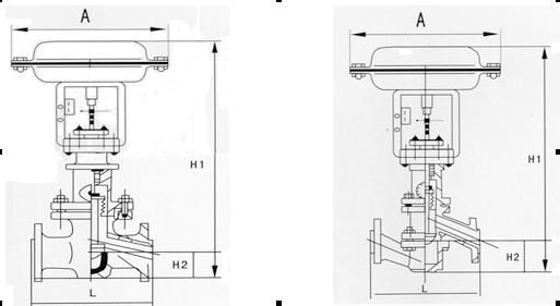
Main connection dimensions:
| Nominal diameter | G3/4" | 20 | 25 | 32 | 40 | 50 | 65 | 80 | 100 | 150 |
|---|---|---|---|---|---|---|---|---|---|---|
| L | 116 | 180 | 185 | 200 | 220 | 250 | 275 | 300 | 350 | 480 |
| A | 285 | 285 | 285 | 285 | 285 | 285 | 360 | 360 | 360 | 470 |
| H | 401 | 445 | 485 | 495 | 523 | 532 | 697 | 710 | 720 | 817 |
| H1 | 50 | 65 | 70 | 80 | 71 | 88 | 102 | 140 | 170 | 190 |
Ordering Notice:
1. Pneumatic fluorine lined single seat regulating valve valve product model and name
2. Pneumatic fluorine lined single seat regulating valve valve with nominal diameter DN
3. Valve connection form of pneumatic fluorine lined single seat regulating valve
4. Pneumatic fluorine lined single seat regulating valve valve valve nominal pressure and pressure difference
5. Pneumatic fluorine lined single seat regulating valve valve rated flow coefficient KV
6. Flow characteristics of pneumatic fluorine lined single seat regulating valve valve valve
7. Pneumatic fluorine lined single seat regulating valve valve suitable temperature
8. Material of valve body and internal components of pneumatic fluorine lined single seat regulating valve
9. Pneumatic fluorine lined single seat regulating valve valve power supply voltage and control signal
10. Does the pneumatic fluorine lined single seat regulating valve come with accessories for your correct selection.
Installation precautions:
The pneumatic fluorine lined single seat regulating valve has two forms: air open valve and air closed valve. The selection should be based on the degree of harm caused to the process production when the pneumatic fluorine lined single seat regulating valve is in the open or closed position when the signal pressure is interrupted. If the valve is in the closed position and the harm is minimal, an air open valve should be selected, otherwise an air closed valve should be selected.
(1) Pneumatic fluorine lined single seat regulating valves should be installed vertically on horizontal pipelines. If horizontal and inclined installation is required in special circumstances, support should generally be added.
(2) When the nominal diameter of the selected pneumatic fluorine lined single seat regulating valve is different from the process pipe diameter, a reducing joint should be installed for connection.
(3) The installation site should have good environmental conditions, with an ambient temperature of -25 to+55 ℃.
(4) Try to avoid installing in places with vibration sources, otherwise necessary anti vibration reinforcement measures should be taken.
(5) During installation, the arrow direction on the valve body or flange must be directed towards the direction of the medium.
(6) Before installation, it is necessary to carefully remove welding slag and other debris from the pipeline; After installation, the valve core should be at its maximum opening, and the pipeline and pneumatic fluorine lined single seat regulating valve should be cleaned again to prevent debris from getting stuck and damaging the throttling components
(7) Pneumatic fluorine lined single seat regulating valves should be installed in a location that is easy to maintain and repair.
(8) The straight pipe section in front of the valve should be as long as possible.
(9) The export piping should use straight pipe sections with a diameter of 3-5 times the diameter of the pipeline.
(10) In order to ensure that the failure of the pneumatic fluorine lined single seat regulating valve and regulating system does not affect production and prevent safety accidents, it is generally necessary to install bypass and bypass valves. The bypass valve cannot be installed directly above the pneumatic fluorine lined single seat regulating valve to prevent corrosive media from leaking into the pneumatic fluorine lined single seat regulating valve. Stop valves need to be installed before and after the pneumatic fluorine lined single seat regulating valve.
(1) Before installation, check that the product model, tag number, and specifications match the requirements. Inspect the entire valve for missing or loose parts.
(2) Prior to installation, clean the pipeline. Ensure there is sufficient straight pipe section at the valve inlet and install a filter. When connecting the valve body to the pipeline flanges, ensure coaxiality.
(3) Thoroughly clean the pipeline before installing the valve.
(4) The installation site should ensure the safety of personnel and equipment, facilitating operation, disassembly, and maintenance.
(5) The valve should be installed vertically upright on horizontal pipelines. If necessary, it can be installed at an angle, but horizontal installation should be avoided. For occasions with heavy valve weight or vibration, use a support frame.
(6) The medium flow direction must align with the arrow on the valve body. The air supply should be dry and oil-free. The valve should be used in environments with temperatures ranging from -20℃ to 55℃.
(1) Cleaning the Valve: For general media, cleaning with water is sufficient. For media harmful to health, first understand their properties and then select an appropriate cleaning method.
(2) Disassembly: Remove rust from exposed rusted parts first. Before derusting, protect the machined surfaces of precision parts such as the valve seat, valve plug, valve stem, and push rod. Use special tools when disassembling the valve seat.
(3) Valve Seat: Minor rust or wear on the sealing surface can be repaired by machining. If damage is severe, replace the seat. However, both repaired and replaced hard sealing surfaces must be lapped.
(4) Valve Stem: If the surface is damaged, it must be replaced.
(5) Damage to Push Rod, Guide, and Sealing Surfaces: Reverse-acting actuators must be replaced; direct-acting actuators can be reused after proper repair.
(6) Compression Spring: If there are cracks or other defects affecting strength, replace it immediately.
(7) Wear Parts: Packing, gaskets, and O-rings must be replaced entirely during each maintenance. Check the valve plug and diaphragm for cracks, aging, or corrosion that may cause future failures. Decide whether to replace them based on inspection results, but the diaphragm service life should not exceed 2-3 years.
(8) When reassembling the valve, ensure alignment. Tighten bolts diagonally and lubricate sliding parts. After reassembly, debug the valve according to the factory test items and methods. During this period, accurately adjust the packing compression force and the valve plug closing position.
-
If the model has not been selected before ordering, please provide us with the operating parameters:
(1) Nominal diameter DN (mm);
(2) Nominal pressure (MPa or bar);
(3) Fluid properties (including medium temperature, viscosity, or acidity/alkalinity);
(4) Pressure before and after the valve (pressure differential);
(5) Requirements for flow characteristics;
(6) Materials of valve body and valve core;
(7) Connection type;
(8) Driving method (provide air supply pressure, driving voltage);
(9) Supporting accessories (for pneumatic valves, it is recommended that users install an air filter triplet and a 2-position 5-way solenoid valve);
(10) On-site working conditions. -
If the product model of our company has been selected by the design unit, please order directly from our production department according to the model;
-
When the application occasion is very important or the pipeline is relatively complex, please provide the design drawings and detailed parameters as much as possible, and our experts will review and check them for you.


