


2. Pneumatic diaphragm regulating valves can be classified according to their operating modes: positive action: air closed normally open type (when the signal pressure increases, the valve position shifts downward), Type B
Reaction: Air opening normally closed type (when the signal pressure increases, the valve position shifts upward), K-type
3. The pneumatic diaphragm regulating valve adopts a balanced valve core, which has small unbalanced force and stable operation. It is suitable for working environments with large pressure difference and slightly large leakage before and after the valve.
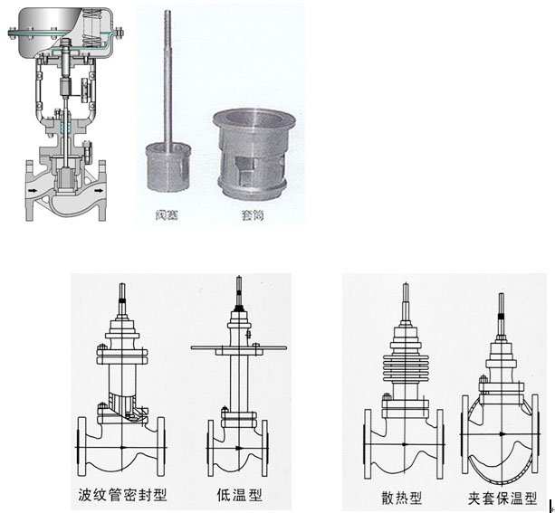
4. The straight through low flow resistance sleeve valve adopts a pressure balanced valve core (double sealing surface or single sealing surface) structure. The valve core is cylindrical, and a certain characteristic window hole is precisely machined. It is guided by the inner circle and top of the sleeve, so the unbalanced force on the valve stem is very small, the operation is stable, and the performance is good. It is a force balanced regulating valve. Suitable for situations where the pressure difference between the front and rear ends of the valve is high. Due to the side guidance of the sleeve on the valve core, the vibration caused by vortex impact is reduced, resulting in low noise, small cavitation flash evaporation effect, and long service life. But the leakage rate of the valve seat is slightly higher than that of a single seat valve.
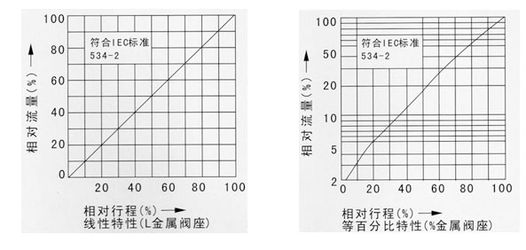
5. By changing the design of the valve core shape; Different valve core window shapes will result in different flow characteristic values: equi percentage (logarithmic), linear.
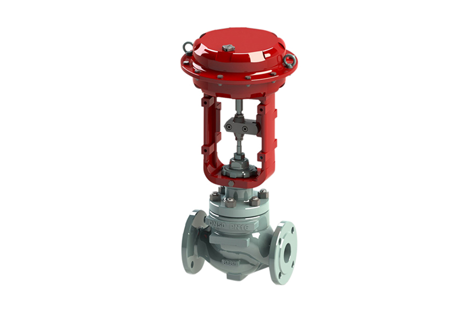
This series of products is widely used in the automation and remote control of industrial production processes such as chemical, petroleum, metallurgy, power plants, textiles, papermaking, and pharmaceuticals.
There are various types including standard type, adjustable cutting type, corrugated pipe sealing type, jacket insulation type, etc. The product pressure rating is PN1.6 4.0 6.4MPa; Nominal diameter DN20~300mm; The applicable fluid temperature ranges from -60 ℃ to+450 ℃; According to the temperature, different valve covers can be divided into room temperature type, high temperature type, and low temperature type.
Pneumatic diaphragm control valve - Main technical parameters of the actuator:
| Model |
ZHA-22 ZHB-22 |
ZHA-23 ZHB-23 |
ZHB-34 ZHB-34 |
ZHA-45 ZHB-45 |
ZHA-56 ZHB-56 |
|---|---|---|---|---|---|
| Effective area cm² | 350 | 350 | 560 | 900 | 1600 |
| Stroke mm | 16 | 25 | 40 | 60 | 100 |
| Spring range KPa | 20 - 100 (standard): 40 - 200; 80 - 240; 20 - 60; 60 - 100 | ||||
| Operation mode | Normal type, with manual handwheel operation type (side-mounted, top-mounted) | ||||
Pneumatic diaphragm control valve - Electro-pneumatic valve positioner:
The electro-pneumatic valve positioner is the main auxiliary instrument for pneumatic actuators in industrial automation. It can be used to improve the linearity of the valve position, overcome the friction of the valve stem, and eliminate the influence of the unbalanced force of the control valve, etc. Thus, it ensures that the valve position is in a proportional relationship with the 0 - 10mA DC or 4 - 20mA current signal transmitted from the control instrument, achieving correct positioning. (There are various model specifications available for selection)
The electro-pneumatic valve positioner of our company is available in models (HEP - 15 explosion-proof type, HEP - 17 intrinsically safe type). It can also be equipped according to different requirements (SVI1000G/IM series, SVI - II series, HEP - 15 series, ZPD2000 series, EP3000 series, EP4000 series, YT1000 series, YT2000 series, SIPART PS2 Siemens series, and intelligent positioner series products).
Pneumatic diaphragm control valve - Performance indicators:
| Item | Index value | Item | Index value | ||||
|---|---|---|---|---|---|---|---|
| Basic error % | Without positioner | ±5.0 |
Start End point deviation % |
Air - closing | Without positioner | Start point | ±5.0 |
| With positioner | ±1.0 | End point | ±2.5 | ||||
| Hysteresis % | Without positioner | ≤3.0 | With positioner | Start point | ±1.0 | ||
| End point | ±1.0 | ||||||
| With positioner | ≤1.0 | Air - opening | Without positioner | Start point | ±2.5 | ||
| End point | ±5.0 | ||||||
| Dead zone % | Without positioner | ≤3.0 | With positioner | Start point | ±1.0 | ||
| End point | ±1.0 | ||||||
| With positioner | ≤0.4 | Permissible leakage L/h | 1×10⁻³×Valve rated capacity | ||||
| Rated stroke deviation % | ±2.5 | ||||||
Note: This product complies with the GB/T4213 - 92 national standard.
Pneumatic diaphragm control valve - Permissible differential pressure: MPa
|
Switch mode |
Actuator model |
Spring range KPa |
Air source pressure KPa |
Required accessories |
Nominal diameter (Valve seat diameter) mm | |||||||||
|---|---|---|---|---|---|---|---|---|---|---|---|---|---|---|
| 25 | 40 | 50 | 65 | 80 | 100 | 150 | 200 | 250 | 300 | |||||
|
Air closing |
ZHA - 22 |
20 - 100 20 - 100 40 - 200 |
0.14 0.25 0.40 |
- P P or R |
3.00 6.4 6.4 |
|
|
|
|
|
|
|
|
|
| ZHA - 23 |
20 - 100 20 - 100 40 - 200 |
0.14 0.25 0.40 |
- P P or R |
|
2.25 6.4 6.4 |
1.95 6.4 6.4 |
|
|
|
|
|
|
|
|
| ZHA - 34 |
20 - 100 20 - 100 40 - 200 |
0.14 0.25 0.40 |
- P P or R |
|
|
|
2.36 6.4 6.4 |
2.04 6.4 6.4 |
1.67 6.4 6.4 |
|
|
|
|
|
| ZHA - 45 |
20 - 100 20 - 100 40 - 200 |
0.14 0.25 0.40 |
- P P or R |
|
|
|
|
|
|
1.41 6.4 6.4 |
1.14 6.4 6.4 |
|
|
|
|
Air opening |
ZHA - 22 |
20 - 100 40 - 200 80 - 240 |
0.14 0.25 0.40 |
- P or R P |
|
1.5 4.5 6.4 |
|
|
|
|
|
|
|
|
| ZHA - 23 |
20 - 100 40 - 200 80 - 240 |
0.14 0.25 0.40 |
- P or R P |
|
|
1.13 3.38 6.40 |
0.98 2.93 6.4 |
|
|
|
|
|
|
|
| ZHA - 34 |
20 - 100 40 - 200 80 - 240 |
0.14 0.25 0.40 |
- P or R P |
|
|
|
1.18 3.54 6.4 |
1.02 3.06 6.4 |
0.84 2.51 5.85 |
|
|
|
|
|
| ZHA - 45 |
20 - 100 40 - 200 80 - 240 |
0.14 0.25 0.40 |
- P or R P |
|
|
|
|
|
|
0.71 2.12 4.94 |
0.57 1.71 4.00 |
|
|
|
Note: 1) P - Valve positioner; R - Pressure relay;
2) The permissible differential pressure is the maximum value of P when the valve is closed and P2 = 0;
3) If the permissible differential pressure is unclear or the maximum working differential pressure exceeds the listed range, please contact us.
Pneumatic diaphragm control valve - Main part materials, applicable temperature, and medium:
| Material code | C (WCB) | P (304) | R (316) | |
|---|---|---|---|---|
|
Main parts |
Valve body, valve cover | WCB (ZG230 - 450) | ZG1Cr18Ni9Ti (304) | ZG1Cr18Ni12Mo2Ti (304) |
| Valve core, valve seat | 1Cr18Ni9Ti (304) or Stellite alloy surfacing | 1Cr18Ni9Ti (304) or Stellite alloy surfacing | 1Cr18Ni12Mo2Ti or Stellite alloy surfacing | |
| Valve stem | 2Cr13 | 1Cr18Ni9Ti | 1Cr18Ni12Mo2Ti | |
| Packing | V - type polytetrafluoroethylene, flexible graphite, stainless - steel bellows | |||
| Gasket | Reinforced polytetrafluoroethylene, stainless - steel gasket, metal graphite wound gasket | |||
| Upper and lower diaphragm covers | A3 steel plate stamping | |||
| Corrugated diaphragm | Nitrile rubber with reinforced polyester fabric | |||
| Spring | 60Si2Mn | |||
| Push rod, bushing | 2Cr13 | |||
| Bush | Polyurethane (for reverse action) | |||
|
Applicable working conditions |
Applicable medium | Water, steam, oil, gas, and liquid | Nitric acid, alkali, corrosive gas, and liquid | Acetic acid, etc., corrosive gas, and liquid |
| Normal temperature type | - 30~+250 F4: ≤200℃ | - 40~+250 F4: ≤200℃ | - 40~+250℃ F4: ≤200℃ | |
| High - temperature type | - 30~+450℃ | - 40~+550℃ | - 40~+550℃ | |
| Low - temperature type |
|
- 40~ - 60℃, - 60~ - 100℃ | ||
Pneumatic diaphragm control valve - Flow characteristic diagram:
Pneumatic diaphragm control valve - Main technical parameters:
| Nominal diameter mm | 20 | 25 | 32 | 40 | 50 | 65 | 80 | 100 | 125 | 150 | 200 | 250 | 300 | |
|---|---|---|---|---|---|---|---|---|---|---|---|---|---|---|
| Valve seat diameter mm | 20 | 25 | 32 | 40 | 50 | 65 | 80 | 100 | 125 | 150 | 200 | 250 | 300 | |
|
Rated flow coefficient Kv |
Linear | 6.9 | 11 | 17.6 | 27.5 | 44 | 69 | 110 | 176 | 275 | 440 | 690 | 1100 | 1760 |
| Equal percentage | 6.3 | 10 | 16 | 25 | 40 | 63 | 100 | 160 | 250 | 400 | 630 | 1000 | 1600 | |
| Rated stroke L (mm) | 10 | 16 | 25 | 40 | 60 | 100 | ||||||||
| Actuator model | ZHA/B - 22 | ZHA/B - 22 | ZHA/B - 23 | ZHA/B - 34 | ZHA/B - 45 | ZHA/B - 56 | ||||||||
| Diaphragm effective area Ae (cm²) | 350 | 350 | 350 | 560 | 900 | 1600 | ||||||||
| Air source pressure Ps (MPa) | 0.14~0.4 | |||||||||||||
| Signal range Pr (KPa) | 20~100, 40~200, 80~240 Segment amplitude: 20~60, 60~100 | |||||||||||||
| Electrical signal | 4~20mA DC or 0~10mA DC | |||||||||||||
| Action mode | Air - opening (K) type, Air - closing (B) type | |||||||||||||
| Flow characteristic | Linear, equal percentage, quick - opening | |||||||||||||
| Permissible leakage (L/h) | Hard seal: 1×10⁻³×Valve rated capacity | |||||||||||||
| Inherent adjustable ratio R | 50:1 | |||||||||||||
| Air source connector | M16×1.5 | |||||||||||||
| Nominal pressure PN (MPa) | 1.6 2.5 4.0 6.4 | |||||||||||||
Product application specifications
Performance: GB/T4213 - 92, JB/T57218 - 94; Structural length: GB/T12221 - 05; Materials: GB/T12228~12230Flange connection: JB/T79 - 94, GB/T9113
Complies with: IEC60534 standard
Pneumatic diaphragm control valve - Overall dimensions:
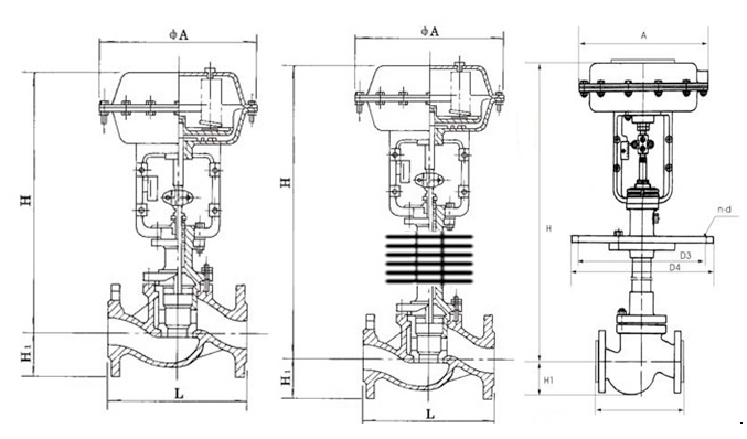
| Nominal diameter (mm) | 20 | 25 | 32 | 40 | 50 | 65 | 80 | 100 | 125 | 150 | 200 | 250 | 300 | ||
|---|---|---|---|---|---|---|---|---|---|---|---|---|---|---|---|
| L (mm) | PN1.6MPa | 181 | 184 | 205 | 222 | 254 | 276 | 298 | 352 | 410 | 451 | 600 | 670 | 735 | |
| PN4.0MPa | 194 | 200 | 210 | 235 | 267 | 292 | 317 | 368 | 425 | 473 | 615 | 685 | 750 | ||
| PN6.4MPa | 205 | 210 | 220 | 251 | 286 | 311 | 337 | 394 | 440 | 508 | 650 | 700 | 765 | ||
| H1 (mm) | PN1.6MPa | 53 | 58 | 68 | 73 | 80 | 90 | 98 | 108 | 123 | 140 | 168 | 203 | 230 | |
| H1 (mm) | PN4.0MPa | 53 | 58 | 68 | 73 | 80 | 90 | 98 | 115 | 135 | 150 | 188 | 223 | 255 | |
| H1 (mm) | PN6.4MPa | 63 | 68 | 75 | 83 | 88 | 100 | 105 | 125 | 148 | 170 | 203 | 235 | 265 | |
| H (mm)≈ | Normal temperature type | 398 | 410 | 454 | 457 | 460 | 610 | 622 | 640 | 846 | 870 | 890 | 1203 | 1234 | |
| High - temperature type | 548 | 560 | 604 | 520 | 627 | 790 | 807 | 850 | 1096 | 1130 | 1150 | 1523 | 1554 | ||
| Low - temperature type | - 100℃ | H2 | 500 | 600 | 700 |
|
|
||||||||
| H≈ | 926 | 935 | 974 | 1082 | 1090 | 1240 | 1252 | 1275 | 1596 | 1620 | 1640 |
|
|
||
| ΦA (mm) | 285 | 360 | 470 |
|
|
||||||||||
(1) Before installation, check that the product model, tag number, and specifications match the requirements. Inspect the entire valve for missing or loose parts.
(2) Prior to installation, clean the pipeline. Ensure there is sufficient straight pipe section at the valve inlet and install a filter. When connecting the valve body to the pipeline flanges, ensure coaxiality.
(3) Thoroughly clean the pipeline before installing the valve.
(4) The installation site should ensure the safety of personnel and equipment, facilitating operation, disassembly, and maintenance.
(5) The valve should be installed vertically upright on horizontal pipelines. If necessary, it can be installed at an angle, but horizontal installation should be avoided. For occasions with heavy valve weight or vibration, use a support frame.
(6) The medium flow direction must align with the arrow on the valve body. The air supply should be dry and oil-free. The valve should be used in environments with temperatures ranging from -20℃ to 55℃.
(1) Cleaning the Valve: For general media, cleaning with water is sufficient. For media harmful to health, first understand their properties and then select an appropriate cleaning method.
(2) Disassembly: Remove rust from exposed rusted parts first. Before derusting, protect the machined surfaces of precision parts such as the valve seat, valve plug, valve stem, and push rod. Use special tools when disassembling the valve seat.
(3) Valve Seat: Minor rust or wear on the sealing surface can be repaired by machining. If damage is severe, replace the seat. However, both repaired and replaced hard sealing surfaces must be lapped.
(4) Valve Stem: If the surface is damaged, it must be replaced.
(5) Damage to Push Rod, Guide, and Sealing Surfaces: Reverse-acting actuators must be replaced; direct-acting actuators can be reused after proper repair.
(6) Compression Spring: If there are cracks or other defects affecting strength, replace it immediately.
(7) Wear Parts: Packing, gaskets, and O-rings must be replaced entirely during each maintenance. Check the valve plug and diaphragm for cracks, aging, or corrosion that may cause future failures. Decide whether to replace them based on inspection results, but the diaphragm service life should not exceed 2-3 years.
(8) When reassembling the valve, ensure alignment. Tighten bolts diagonally and lubricate sliding parts. After reassembly, debug the valve according to the factory test items and methods. During this period, accurately adjust the packing compression force and the valve plug closing position.
-
If the model has not been selected before ordering, please provide us with the operating parameters:
(1) Nominal diameter DN (mm);
(2) Nominal pressure (MPa or bar);
(3) Fluid properties (including medium temperature, viscosity, or acidity/alkalinity);
(4) Pressure before and after the valve (pressure differential);
(5) Requirements for flow characteristics;
(6) Materials of valve body and valve core;
(7) Connection type;
(8) Driving method (provide air supply pressure, driving voltage);
(9) Supporting accessories (for pneumatic valves, it is recommended that users install an air filter triplet and a 2-position 5-way solenoid valve);
(10) On-site working conditions. -
If the product model of our company has been selected by the design unit, please order directly from our production department according to the model;
-
When the application occasion is very important or the pipeline is relatively complex, please provide the design drawings and detailed parameters as much as possible, and our experts will review and check them for you.


