


2. Thrust bearings reduce the friction torque of the valve stem, allowing for long-term balanced and flexible operation of the valve stem.
3. The valve seat has good sealing performance and is made of sealing rings made of materials such as polytetrafluoroethylene. The structure is easy to seal, and the sealing ability of the ball valve increases with the increase of medium pressure.
4. The valve stem seal is reliable. As the valve stem only rotates without lifting, the packing seal of the valve stem is not easily damaged, and the sealing ability increases with the increase of medium pressure.
5. Due to the good self-lubricating properties of materials such as polytetrafluoroethylene, the friction loss with the ball is small, and the service life of the ball valve is long.
6. The bottom mounted valve stem and the protruding step at the head of the valve stem prevent the valve stem from spraying out. In the event of a fire causing damage to the valve stem seal, the protruding step can also form a metal contact with the valve body to ensure the valve stem seal.
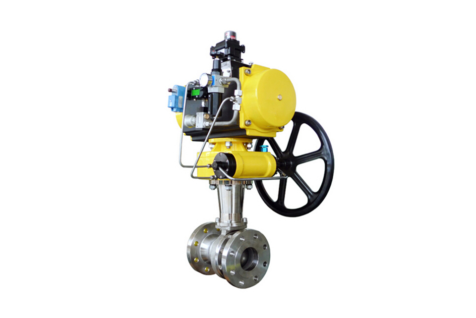
Technical Specification for High-Temperature Pneumatic Control Ball Valve
| Design Basis | GB Standard | |
|---|---|---|
| Design Standard | GB/12237 | |
| Structural Length | Flange Connection | GB/12221 |
| Connection Flange Dimensions | GB/9113, JB/T79 | |
| Test and Inspection | JB/T9002 | |
※ Note: The structural length and connection flange dimensions of the series ball valves can be designed and manufactured according to user requirements.
Material Table for Main Parts of High-Temperature Pneumatic Control Ball Valve
| Serial Number | Part Name | Material | ||
|---|---|---|---|---|
| C | D | R | ||
| 1 | Right Valve Body | WCB | ZG1Cr18Ni9Ti | ZG1Cr18Ni12M02Ti |
| 2 | Nut | 35 | 1Cr18Ni9Ti | 1Cr18Ni9Ti |
| 3 | Gasket | PTFE | PTFE | PTFE |
| 4 | Stud | 35 | 1Cr18Ni9Ti | 1Cr18Ni9Ti |
| 5 | Valve Body | WCB | ZG1Cr18Ni9Ti | ZG1Cr18Ni12Mo2Ti |
| 6 | Valve Seat | PTFE | PTFE | PTFE |
| 7 | Ball | 1Cr18Ni9Ti | 1Cr18Ni9Ti | 1Cr18Ni12Mo2Ti |
| 8 | Valve Stem | 1Cr13 | 1Cr18Ni9Ti | 1Cr18Ni12Mo2Ti |
| 9 | Gasket | PTFE | PTFE | PTFE |
| 1 | Packing | PTFE | PTFE | PTFE |
| 11 | Bushing | PTFE | PTFE | PTFE |
| 12 | Gland | WCB | ZG1Cr18Ni9Ti | ZG1Cr18Ni12Mo2Ti |
| 13 | Bolt | 35 | 1Cr18Ni9Ti | 1Cr18Ni9Ti |
| 14 | Bolt | 35 | 1Cr18Ni9Ti | 1Cr18Ni9Ti |
| 15 | Connection Bracket | 1Cr18Ni9Ti | 1Cr18Ni9Ti | 1Cr18Ni9Ti |
| 16 | Bolt | 35 | 1Cr18Ni9Ti | 1Cr18Ni9Ti |
| 17 | Connection Sleeve | 35 | 1Cr18Ni9Ti | 1Cr18Ni9Ti |
| 18 | Pneumatic Device |
|
|
|
| 19 | Position Indicator | Plastic | Plastic | Plastic |
※ Note: The materials of the main parts and sealing rings of the series ball valves can be designed and selected according to the actual working conditions or special user requirements.
Main Dimensions of Appearance and Connection Flange of High-Temperature Pneumatic Control Ball Valve: Q641(F、N、P)-16(1.6Mpa)
|
Nominal Diameter DN |
Dimensions of Appearance | Dimensions of Connection Flange | ||||||||
|---|---|---|---|---|---|---|---|---|---|---|
|
L |
L1 |
L2 |
H |
D |
D1 |
D2 |
C |
f |
n-φd |
|
| 15 | 130 | 140/178 | 62/75 | 185/191 | 95 | 65 | 46 | 14 | 2 | 4-φ14 |
| 20 | 130 | 140/178 | 62/75 | 191/197 | 105 | 75 | 56 | 16 | 2 | 4-φ14 |
| 25 | 140 | 140/214 | 62/91 | 193/227 | 115 | 85 | 65 | 16 | 2 | 4-φ14 |
| 32 | 165 | 164/214 | 75/91 | 212/240 | 140 | 100 | 76 | 18 | 3 | 4-φ18 |
| 40 | 165 | 164/246 | 75/101 | 217/255 | 150 | 110 | 84 | 18 | 3 | 4-φ18 |
| 50 | 203 | 190/295 | 91/112 | 260/286 | 165 | 125 | 99 | 20 | 3 | 4-φ18 |
| 65 | 222 | 210/295 | 101/112 | 293/309 | 185 | 145 | 118 | 20 | 3 | 4-φ18 |
| 80 | 241 | 247/395 | 112/139 | 323/349 | 200 | 160 | 132 | 20 | 3 | 8-φ18 |
| 100 | 305 | 276/478 | 127/176 | 382/438 | 220 | 180 | 156 | 22 | 3 | 8-φ18 |
| 125 | 356 | 348/562 | 159/206 | 468/534 | 250 | 210 | 184 | 22 | 3 | 8-φ18 |
| 150 | 394 | 378/724 | 176/228 | 510/582 | 285 | 240 | 211 | 24 | 3 | 8-φ22 |
| 200 | 457 | 524/928 | 228/275 | 655/702 | 340 | 295 | 266 | 24 | 3 | 12-φ22 |
Main Dimensions of Appearance and Connection Flange of High-Temperature Pneumatic Control Ball Valve: Q641(F、N、P)-25(2.5Mpa)
| Nominal Diameter DN | Dimensions of Appearance | Dimensions of Connection Flange | Actuator Model | ||||||||
|---|---|---|---|---|---|---|---|---|---|---|---|
| L | L1 | L2 | H | D | D1 | D2 | C | f | n-φd | ||
| 15 | 140 | 1401/178 | 62/75 | 1851/191 | 95 | 65 | 46 | 14 | 2 | 4-φ14 | GTD52/GTE65 |
| 20 | 152 | 1401/178 | 62/75 | 1911/197 | 105 | 75 | 56 | 16 | 2 | 4-φ14 | GTD52/GTE65 |
| 25 | 165 | 164/214 | 75/91 | 199/227 | 115 | 85 | 65 | 16 | 3 | 4-φ14 | GTD65/GTE80 |
| 32 | 178 | 164/246 | 751/101 | 212/250 | 140 | 100 | 76 | 18 | 3 | 4-φ18 | GTD65/GTE90 |
| 40 | 190 | 190/246 | 911/101 | 245/255 | 150 | 110 | 84 | 18 | 3 | 4-φ18 | GTD80/GTE90 |
| 50 | 216 | 210/295 | 1011/112 | 270/286 | 165 | 125 | 99 | 20 | 3 | 4-φ18 | GTD90/GTE100 |
| 65 | 241 | 247/340 | 1121/112 | 309/330 | 185 | 145 | 118 | 22 | 3 | 8-φ18 | GTD100/GTE115 |
| 80 | 283 | 276/395 | 127/139 | 344/349 | 200 | 160 | 132 | 24 | 3 | 8-φ18 | GTD115/GTE125 |
| 100 | 305 | 348/478 | 1591/176 | 421/438 | 235 | 190 | 156 | 24 | 3 | 8-φ22 | GTD145/GTE160 |
| 125 | 381 | 378/562 | 176/206 | 485/534 | 270 | 220 | 184 | 26 | 3 | 8-φ26 | GTD160/GTE190 |
| 150 | 403 | 432/724 | 206/228 | 559/582 | 300 | 250 | 211 | 28 | 3 | 8-φ26 | GTD190/GTE210 |
| 200 | 502 | 524/928 | 228/275 | 655/702 | 360 | 310 | 274 | 30 | 3 | 12-φ26 | GTD210/GTE255 |
Main Dimensions of Appearance and Connection Flange of High-Temperature Pneumatic Control Ball Valve: Q641(F、N、P)-40(4.0Mpa)
| Nominal Diameter DN | Dimensions of Appearance | Dimensions of Connection Flange | Actuator Model | |||||||||
|---|---|---|---|---|---|---|---|---|---|---|---|---|
|
L |
L1 |
L2 |
H |
D |
D1 |
D2 |
D3 |
C |
f |
n-φd |
||
| 15 | 140 | 1401/178 | 62/75 | 1851/191 | 95 | 65 | 46 | 40×4 | 14 | 2 | 4-φ14 | GTD52/GTE65 |
| 20 | 152 | 164/214 | 75/91 | 197/225 | 105 | 75 | 56 | 51×4 | 16 | 2 | 4-φ14 | GTD65/GTE80 |
| 25 | 165 | 164/214 | 75/91 | 199/227 | 115 | 85 | 65 | 58×4 | 16 | 3 | 4-φ14 | GTD65/GTE80 |
| 32 | 178 | 190/295 | 911/112 | 240/266 | 140 | 100 | 76 | 66×4 | 18 | 3 | 4-φ18 | GTD80/GTE100 |
| 40 | 190 | 210/295 | 1011/112 | 255/271 | 150 | 110 | 84 | 76×4 | 18 | 3 | 4-φ18 | GTD90/GTE100 |
| 50 | 216 | 247/340 | 1121/127 | 286/307 | 165 | 125 | 99 | 88×4 | 20 | 3 | 4-φ18 | GTD100/GTE115 |
| 65 | 241 | 276/398 | 1271/139 | 330/335 | 185 | 145 | 118 | 110×4 | 22 | 3 | 8-φ18 | GTD115/GTE125 |
| 80 | 283 | 308/438 | 139/159 | 349/383 | 200 | 160 | 132 | 121×4 | 24 | 4 | 8-φ18 | GTD125/GTE145 |
| 100 | 305 | 348/562 | 159/206 | 421/487 | 235 | 190 | 156 | 150×4.5 | 24 | 4 | 8-φ22 | GTD145/GTE190 |
| 125 | 381 | 432/724 | 176/228 | 485/557 | 270 | 220 | 184 | 176×4.5 | 26 | 4 | 8-φ26 | GTD160/GTE210 |
| 150 | 403 | 524/928 | 228/275 | 582/629 | 300 | 250 | 211 | 204×4.5 | 28 | 4 | 8-φ26 | GTD210/GTE255 |
| 200 | 502 | 6481/1033 | 275/324 | 702/750 | 375 | 320 | 284 | 260×4.5 | 34 | 5 | 12-φ30 | GTD255/GTE300 |
※ Note: The structural length and connection flange dimensions of the series ball valves can be designed and manufactured according to the JB/T79 standard or user requirements.
※ Note: The data ×××/××× represent the double-acting and single-acting (spring return) types of the pneumatic actuator respectively.
※ Note: The actuator model may vary according to different valve torques and working media, and the relevant dimensions will change accordingly.
(1) Before installation, check that the product model, tag number, and specifications match the requirements. Inspect the entire valve for missing or loose parts.
(2) Prior to installation, clean the pipeline. Ensure there is sufficient straight pipe section at the valve inlet and install a filter. When connecting the valve body to the pipeline flanges, ensure coaxiality.
(3) Thoroughly clean the pipeline before installing the valve.
(4) The installation site should ensure the safety of personnel and equipment, facilitating operation, disassembly, and maintenance.
(5) The valve should be installed vertically upright on horizontal pipelines. If necessary, it can be installed at an angle, but horizontal installation should be avoided. For occasions with heavy valve weight or vibration, use a support frame.
(6) The medium flow direction must align with the arrow on the valve body. The air supply should be dry and oil-free. The valve should be used in environments with temperatures ranging from -20℃ to 55℃.
(1) Cleaning the Valve: For general media, cleaning with water is sufficient. For media harmful to health, first understand their properties and then select an appropriate cleaning method.
(2) Disassembly: Remove rust from exposed rusted parts first. Before derusting, protect the machined surfaces of precision parts such as the valve seat, valve plug, valve stem, and push rod. Use special tools when disassembling the valve seat.
(3) Valve Seat: Minor rust or wear on the sealing surface can be repaired by machining. If damage is severe, replace the seat. However, both repaired and replaced hard sealing surfaces must be lapped.
(4) Valve Stem: If the surface is damaged, it must be replaced.
(5) Damage to Push Rod, Guide, and Sealing Surfaces: Reverse-acting actuators must be replaced; direct-acting actuators can be reused after proper repair.
(6) Compression Spring: If there are cracks or other defects affecting strength, replace it immediately.
(7) Wear Parts: Packing, gaskets, and O-rings must be replaced entirely during each maintenance. Check the valve plug and diaphragm for cracks, aging, or corrosion that may cause future failures. Decide whether to replace them based on inspection results, but the diaphragm service life should not exceed 2-3 years.
(8) When reassembling the valve, ensure alignment. Tighten bolts diagonally and lubricate sliding parts. After reassembly, debug the valve according to the factory test items and methods. During this period, accurately adjust the packing compression force and the valve plug closing position.
-
If the model has not been selected before ordering, please provide us with the operating parameters:
(1) Nominal diameter DN (mm);
(2) Nominal pressure (MPa or bar);
(3) Fluid properties (including medium temperature, viscosity, or acidity/alkalinity);
(4) Pressure before and after the valve (pressure differential);
(5) Requirements for flow characteristics;
(6) Materials of valve body and valve core;
(7) Connection type;
(8) Driving method (provide air supply pressure, driving voltage);
(9) Supporting accessories (for pneumatic valves, it is recommended that users install an air filter triplet and a 2-position 5-way solenoid valve);
(10) On-site working conditions. -
If the product model of our company has been selected by the design unit, please order directly from our production department according to the model;
-
When the application occasion is very important or the pipeline is relatively complex, please provide the design drawings and detailed parameters as much as possible, and our experts will review and check them for you.


