


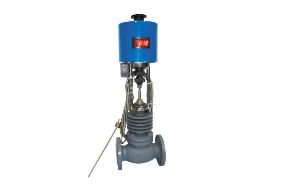
The electric temperature regulating valve consists of three parts: the main valve, the intelligent actuator, and the sensor. According to user needs, there are two types of structures: heating type and cooling type.
Structure and principle of heating type regulating valve
Before work, the main valve core is in the half open position and the sensor is in its natural state. Connect the power supply, and the main valve core heats the thermal storage tank. When the temperature rises to the corresponding set value, the sensor generates a linear signal input to the actuator, which drives the valve core to gradually open, causing the medium to flow into the heat storage tank according to the parabolic characteristic and heat up to the set value. In this way, the controlled medium is always controlled within the set temperature range, thus achieving the purpose of temperature control.
Note: Commonly referred to as heating type and cooling type. This can be achieved by simply replacing the valve core structure in this valve.
| Nominal diameter (mm) | 15 | 20 | 25 | 32 | 40 | 50 | 65 | 80 | 100 | 125 | 150 | 200 | |
|---|---|---|---|---|---|---|---|---|---|---|---|---|---|
| Nominal pressure PN (MPa) | 1.6 4.0 | ||||||||||||
| Flow capacity (m³/h) | 5 | 7 | 10 | 16 | 25 | 40 | 63 | 100 | 160 | 250 | 400 | 630 | |
| Rated stroke (mm) | 6 | 8 | 10 | 14 | 20 | 30 | 30 | 40 | |||||
| Temperature adjustment range (°C) | 0~120 : 100~250 | ||||||||||||
| Adjustment accuracy (°C) | ±1~±5 | ||||||||||||
| Medium used | Steam, water, oil, gas | ||||||||||||
| Allowable leakage | Hard seal | 10⁻⁴ × valve rated capacity | |||||||||||
| Soft seal | “ 0 ” | ||||||||||||
| Capillary length | 3m, 5m, 10m | ||||||||||||
| Thermowell insertion depth | 270, 430, 630 | ||||||||||||
| Threaded interface | 3/4″ 1″ | ||||||||||||
Installation of electric temperature control valve
(1) Before installation, the pipeline should be strictly decontaminated, and impurities such as welding slag should be blown clean. Otherwise, the valve will be seriously damaged.
(2) The temperature control valve should be vertically installed on the horizontal pipeline, and the medium flow direction should be consistent with the arrow direction on the valve body.
(3) To ensure continuous operation during the automatic control system operation or valve maintenance, a bypass valve should be installed. A filter and a pressure gauge must be installed in front of the valve, and a thermometer should be installed near the sensor for on - site monitoring and temperature setting.
(4) The sensor must be completely immersed in the controlled medium and installed horizontally or obliquely upward.
Commissioning of electric temperature control valve
(1) Connect to the 220V AC power supply. Open the main valve and slowly open the stop valve in front of the valve.
(2) Connect the thermowell wire to the specified terminal.
(3) Observe whether the change value of the set temperature is within the allowable range. If it is found to be too high or too low, remove the actuator housing and toggle the temperature setting switch (fine - tune only). Adjust repeatedly until the control temperature is within the allowable range.
(4) The valve should be used in a place with an ambient temperature of - 25~55°C, and attention should be paid to moisture - proofing.
Model numbering instructions
| Product category | Z |
|
|
|
|
|
|
Actuator category |
|---|---|---|---|---|---|---|---|---|
|
|
Z |
|
|
|
|
|
Self - operated | |
|
|
W |
|
|
|
|
Temperature | ||
| Adjusting mechanism | P | N | M |
|
Single - seat, double - seat, sleeve control valve | |||
| Mechanism type | E |
|
With electric control drive | |||||
| Nominal pressure | 16 |
|
1.6MPa | |||||
| Auxiliary spool action mode | B | Heating type | ||||||
| K | Cooling type | |||||||
Temperature - controlled electric actuator
In recent years, our factory has developed a new type of temperature - controlled electric actuator according to user needs. It has a unique temperature - control module inside. It receives the temperature signal and valve position signal of the controlled object from the temperature sensor. After rapid calculation, data processing and identification, it immediately converts them into three command signals, which drive the electronic switch to make the actuator in the three states of moving up, moving down and staying in place. The output shaft of the actuator is linked with the valve to control the valve opening, thus becoming a temperature - control valve that can directly realize automatic adjustment and effective control of the temperature of media such as steam, hot water and hot oil. It can be widely used in industrial enterprises such as chemical, petroleum, food and light textile industries, as well as service industries such as hotels, guesthouses and hospitals. After being used in different industries, it has won the love and trust of users and has been accepted and selected by relevant industries.
Features
Only a single - phase AC power supply AC220V and a temperature sensor (thermowell) are required on - site to form a self - contained temperature - control system. It can directly replace the thermowell and self - operated control valve, and there is no need to connect the temperature controller and actuator separately. It is a perfect combination of the adjustment system and the self - operated valve.
The actuator has a highly integrated FDY - 258T temperature - control module, which combines the temperature controller and the actuator into one, realizing mechatronics and simplifying the temperature - control system.
It has a wide range of adaptability and can control the temperature in a wide temperature range.
It has high control accuracy, fast response speed, stable and reliable performance, and a long service life.
It has a compact structure, and is easy to install, commission and use.
Instructions for use
1. Connect the two wires at one end of the thermowell to the H1 and H2 terminals of the temperature controller, and connect the single wire at the other end to the H3 terminal. Connect the two wires of the AC220V power supply to the H4 and H5 terminals respectively.
2. According to the valve diameter, the zero position and full position of the actuator stroke can be adjusted, and it has upper and lower limit functions.
3. The set temperature value can be adjusted according to the indication of the thermometer of the controlled object. When the expected temperature value is reached, make the actuator link the valve at a certain opening. When the actual temperature is higher than the expected temperature value, the actuator reduces the valve opening; when it is lower than the expected value, the actuator increases the valve opening. The control sensitivity can be adjusted as needed.
When placing an order, users must provide our factory with technical data such as the control temperature range and valve diameter.
Our factory's products are commissioned according to the data provided by users. Users only need to make a little adjustment on - site to achieve the temperature - control state.
(1) Before installation, check that the product model, tag number, and specifications match the requirements. Inspect the entire valve for missing or loose parts.
(2) Prior to installation, clean the pipeline. Ensure there is sufficient straight pipe section at the valve inlet and install a filter. When connecting the valve body to the pipeline flanges, ensure coaxiality.
(3) Thoroughly clean the pipeline before installing the valve.
(4) The installation site should ensure the safety of personnel and equipment, facilitating operation, disassembly, and maintenance.
(5) The valve should be installed vertically upright on horizontal pipelines. If necessary, it can be installed at an angle, but horizontal installation should be avoided. For occasions with heavy valve weight or vibration, use a support frame.
(6) The medium flow direction must align with the arrow on the valve body. The air supply should be dry and oil-free. The valve should be used in environments with temperatures ranging from -20℃ to 55℃.
(1) Cleaning the Valve: For general media, cleaning with water is sufficient. For media harmful to health, first understand their properties and then select an appropriate cleaning method.
(2) Disassembly: Remove rust from exposed rusted parts first. Before derusting, protect the machined surfaces of precision parts such as the valve seat, valve plug, valve stem, and push rod. Use special tools when disassembling the valve seat.
(3) Valve Seat: Minor rust or wear on the sealing surface can be repaired by machining. If damage is severe, replace the seat. However, both repaired and replaced hard sealing surfaces must be lapped.
(4) Valve Stem: If the surface is damaged, it must be replaced.
(5) Damage to Push Rod, Guide, and Sealing Surfaces: Reverse-acting actuators must be replaced; direct-acting actuators can be reused after proper repair.
(6) Compression Spring: If there are cracks or other defects affecting strength, replace it immediately.
(7) Wear Parts: Packing, gaskets, and O-rings must be replaced entirely during each maintenance. Check the valve plug and diaphragm for cracks, aging, or corrosion that may cause future failures. Decide whether to replace them based on inspection results, but the diaphragm service life should not exceed 2-3 years.
(8) When reassembling the valve, ensure alignment. Tighten bolts diagonally and lubricate sliding parts. After reassembly, debug the valve according to the factory test items and methods. During this period, accurately adjust the packing compression force and the valve plug closing position.
-
If the model has not been selected before ordering, please provide us with the operating parameters:
(1) Nominal diameter DN (mm);
(2) Nominal pressure (MPa or bar);
(3) Fluid properties (including medium temperature, viscosity, or acidity/alkalinity);
(4) Pressure before and after the valve (pressure differential);
(5) Requirements for flow characteristics;
(6) Materials of valve body and valve core;
(7) Connection type;
(8) Driving method (provide air supply pressure, driving voltage);
(9) Supporting accessories (for pneumatic valves, it is recommended that users install an air filter triplet and a 2-position 5-way solenoid valve);
(10) On-site working conditions. -
If the product model of our company has been selected by the design unit, please order directly from our production department according to the model;
-
When the application occasion is very important or the pipeline is relatively complex, please provide the design drawings and detailed parameters as much as possible, and our experts will review and check them for you.


