


Main component materials
| Component name | Material |
|---|---|
| Valve body, valve cover | WCB(ZG230-450) WCC(ZG270-500) WC6(ZG15CrMo) CF8(304) CF8M(316) CF3(304L) CF3M(316L) |
| Valve core, valve seat | 304(0Cr18Ni9) 316(OCr17Nil2Mo2) 316L(00Cr17Nil4Mo2) and overlay welded with Stellite alloy 17-4PH(Precipitation hardening stainless steel) |
| Packing | PTFE(Polytetrafluoroethylene) R.TFE(Reinforced polytetrafluoroethylene) Grafoil(Flexible graphite) |
| Sealing gasket | PTFE, Flexible graphite with metal insert |
| Valve stem | 304 316 316L 17-4PH |
Note: Other materials can be selected according to the working conditions.
Main technical parameters
| Nominal diameter DN(mm) | 20 | 25 | 32 | 40 | 50 | |||||||||||||
|---|---|---|---|---|---|---|---|---|---|---|---|---|---|---|---|---|---|---|
| Valve seat diameter dn(mm) | 10 | 12 | 15 | 20 | 10 | 12 | 15 | 20 | 25 | 32 | 32 | 40 | 32 | 40 | 50 | |||
| Rated flow coefficient (KV) | Linear | 1.8 | 2.8 | 4.4 | 6.9 | 1.8 | 2.8 | 4.4 | 6.9 | 11 | 17.6 | 17.6 | 27.5 | 17.6 | 27.5 | 44 | ||
| Equal percentage | 1.6 | 2.5 | 4.0 | 6.3 | 1.6 | 2.5 | 4.0 | 6.3 | 10 | 16 | 16 | 25 | 16 | 25 | 40 | |||
| Valve stroke (mm) | 16 | 25 | ||||||||||||||||
| Actuator model | 361LSA-08/381LSA-08/PSL201 | 361LSA-20/381LSA-20/PSL202 | ||||||||||||||||
| Nominal diameter DN(mm) | 65 | 80 | 100 | 125 | 150 | 200 | 250 | |||||||||||
| Valve seat diameter dn(mm) | 65 | 65 | 80 | 65 | 80 | 100 | 125 | 125 | 150 | 150 | 200 | 250 | ||||||
| Rated flow coefficient (KV) | Linear | 69 | 69 | 110 | 69 | 110 | 176 | 275 | 275 | 440 | 440 | 690 | 1100 | |||||
| Equal percentage | 63 | 63 | 100 | 63 | 100 | 160 | 250 | 250 | 400 | 400 | 630 | 900 | ||||||
| Rated stroke L | 40 | 60 | 100 | |||||||||||||||
| Commonly used actuator model |
361LSB-3 |
361LSB-50 381LSB-50 PSL208 |
361LSC-65 381LSC-65 PSL312 |
361LSC-99 381LSC-99 PSL314 |
361LSC-160 381LSC-160 PSL316/320 |
|||||||||||||
| Nominal pressure (PN)/Class | MPa | 1.6, 2.5, 4.0, 6.4(6.3)/2.0, 5.0, 11.0 | ||||||||||||||||
| Bar | 16, 25, 40, 64(63)/20, 50, 110 | |||||||||||||||||
| Lb | ANSI: Class150, Class300, Class600 | |||||||||||||||||
| Inherent flow characteristic | Linear, Equal percentage | |||||||||||||||||
| Inherent adjustable ratio (R) | 50:1 | |||||||||||||||||
| Signal | Input signal: 4 - 20mA (indicate if input is 1 - 5v); Feedback signal: 4 - 20mA | |||||||||||||||||
| Allowable leakage | Hard valve core; Class IV (10-4×Kv), Soft valve core: Class VI, see GB/T4213-92 | |||||||||||||||||
| Operating temperature t (℃) | Normal temperature type |
|
-20~200, -40~250, -60~250 | |||||||||||||||
| Heat dissipation type | Code: S | -40~350, -60~350 | ||||||||||||||||
| High temperature type | Code: G | 350~595 (Select high temperature materials) | ||||||||||||||||
| Low temperature type | Code: D | D0: -60~-100, D1: -100~-200, D2: -200~-250 | ||||||||||||||||
| Regulating and shut-off type | Code: Q | -40~150 (Valve core with reinforced PTFE) (Used in special cases) | ||||||||||||||||
Note: ① The division of operating temperature is based on the comprehensive factors such as the pressure - temperature rating of the valve body material (GB/T12224-2005), the operating conditions, and the sealing material of the valve. There are slight differences in the division among different countries, and even among different manufacturing companies due to the use of different materials.
The above actuator configuration is based on the conventional configuration. The specific configuration should be determined according to the process parameters, considering the pressure difference, and a reasonable and economical actuator should be selected. The electronic electric actuators can also use the same type of products from other companies.
Overall dimensions
Overall dimensions table of high temperature type electric single-seated control valve
| Nominal diameter | L | H | D | Weight Kg | |||||
|---|---|---|---|---|---|---|---|---|---|
| PN Mpa | Normal temperature | Heat dissipation high temperature | PN1.6 Mpa | PN6.4 Mpa | |||||
| 1.6 | 4.0 | 6.4 | Normal temperature | High temperature | |||||
| 15 | 150 | 230 | 560 | 630 | 225 |
|
12 | 14 | |
| 20 | 150 | 230 | 565 | 635 |
|
25 | 28 | ||
| 25 | 160 | 230 | 570 | 640 | 24 | 28 | 31 | ||
| 32 | 180 | 260 | 595 | 665 | 26 | 29 | 32 | ||
| 40 | 200 | 260 | 655 | 725 | 255 | 36 | 45 | 49 | |
| 50 | 230 | 300 | 660 | 735 | 39 | 49 | 53 | ||
| 65 | 290 | 340 | 760 | 840 | 57 | 76 | 84 | ||
| 80 | 310 | 380 | 770 | 840 | 72 | 95 | 105 | ||
| 100 | 350 | 430 | 770 | 850 | 311 | 85 | 100 | 120 | |
| 125 | 400 | 500 | 1045 | 1135 | 150 | 175 | 190 | ||
| 150 | 480 | 550 | 1100 | 1190 | 187 | 231 | 251 | ||
| 200 | 600 | 650 | 1285 | 1380 | 242 | 365 | 355 | ||
| 250 | 730 | 775 | 1335 | 1435 |
|
345 | 398 | 495 | |
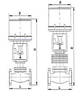
Note:
① To facilitate maintenance, please reserve 200 - 300mm space above the valve so that the actuator can be removed without removing the valve.
② Take the 361L type actuator as an example.
Overall dimensions table of high temperature type electric single-seated control valve
| Nominal diameter | D | Dn | -100℃ | -200℃ | -250℃ | D3 | D4 | n-Φd | Weight Kg | |||
|---|---|---|---|---|---|---|---|---|---|---|---|---|
| H2 | H | H2 | H | H2 | H | |||||||
| 15 | 225 | 290 | 500 | 932 | 700 | 1132 | 900 | 1332 | 260 | 290 | 8-14 | 21 |
| 20 | 290 | 1050 | 1250 | 1450 | 35 | |||||||
| 25 | 290 | 1080 | 1280 | 1480 | 39 | |||||||
| 32 | 315 | 1100 | 1300 | 1500 | 285 | 315 | 41 | |||||
| 40 | 255 | 335 | 1225 | 1425 | 1625 | 305 | 335 | 8-16 | 59 | |||
| 50 | 370 | 1263 | 1463 | 1663 | 340 | 370 | 65 | |||||
| 65 | 400 | 600 | 1426 | 800 | 1626 | 1000 | 1826 | 370 | 400 | 10-16 | 95 | |
| 80 | 435 | 1431 | 1631 | 1831 | 405 | 435 | 108 | |||||
| 100 | 490 | 1450 | 1650 | 1850 | 460 | 490 | 12-18 | 138 | ||||
| 125 | 310 | 555 | 700 | 1755 | 900 | 1955 | 1100 | 2155 | 525 | 555 | 14-18 | 223 |
| 150 | 630 | 1785 | 1985 | 2185 | 590 | 630 | 16-18 | 282 | ||||
| 200 | 740 | 1821 | 2021 | 2221 | 700 | 740 | 18-18 | 395 | ||||
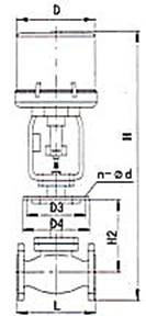
Note:
① Take the 361L type actuator as an example. H2 can also be specified by the design institute or the user.
② The dimension L is shown in the above figure.
Connection dimensions and standards
Flanges are in accordance with GB/T9113-2000 (default standard).
It can also be in accordance with JB/T79.1-94, JB/T79.2-94, or HG20592~HG20635-2009.
Flange sealing surface type: PN16, PN25 are raised face flanges, PN40, PN64(63) are male and female face flanges, and the valve body is a female face flange.
Flange end distance is in accordance with GB12221-2005 (other standards must be specified).
Welded connection groove is in accordance with GB12224-2005.
The valve body flange and flange end distance can be manufactured according to the standards specified by the user, such as ANSI, JIS, DIN, etc.
Model numbering instructions
ZDLP- K(B)
Actuator category; D: Electronic; L: Linear stroke; P: Single-seated control valve
Pressure level: For example, 16: 1.6MPa; K(B) Electric open(close) type
ZDLPQ-K(B) Q: Regulating and shut-off type
ZDLP-K(B)GG: High temperature type
ZDLP-K(B)WW: Bellows sealed type
ZDLP-K(B)JJ: Jacketed insulation type
ZDLP-K(B)DD: Low temperature type
ZDLP-K(B)SS: Heat dissipation type
ZDLP-K(B)WSWS: Bellows sealed heat dissipation type
ZDLPⅡ-K(B)Ⅱ: Low noise type
(1) Before installation, check that the product model, tag number, and specifications match the requirements. Inspect the entire valve for missing or loose parts.
(2) Prior to installation, clean the pipeline. Ensure there is sufficient straight pipe section at the valve inlet and install a filter. When connecting the valve body to the pipeline flanges, ensure coaxiality.
(3) Thoroughly clean the pipeline before installing the valve.
(4) The installation site should ensure the safety of personnel and equipment, facilitating operation, disassembly, and maintenance.
(5) The valve should be installed vertically upright on horizontal pipelines. If necessary, it can be installed at an angle, but horizontal installation should be avoided. For occasions with heavy valve weight or vibration, use a support frame.
(6) The medium flow direction must align with the arrow on the valve body. The air supply should be dry and oil-free. The valve should be used in environments with temperatures ranging from -20℃ to 55℃.
(1) Cleaning the Valve: For general media, cleaning with water is sufficient. For media harmful to health, first understand their properties and then select an appropriate cleaning method.
(2) Disassembly: Remove rust from exposed rusted parts first. Before derusting, protect the machined surfaces of precision parts such as the valve seat, valve plug, valve stem, and push rod. Use special tools when disassembling the valve seat.
(3) Valve Seat: Minor rust or wear on the sealing surface can be repaired by machining. If damage is severe, replace the seat. However, both repaired and replaced hard sealing surfaces must be lapped.
(4) Valve Stem: If the surface is damaged, it must be replaced.
(5) Damage to Push Rod, Guide, and Sealing Surfaces: Reverse-acting actuators must be replaced; direct-acting actuators can be reused after proper repair.
(6) Compression Spring: If there are cracks or other defects affecting strength, replace it immediately.
(7) Wear Parts: Packing, gaskets, and O-rings must be replaced entirely during each maintenance. Check the valve plug and diaphragm for cracks, aging, or corrosion that may cause future failures. Decide whether to replace them based on inspection results, but the diaphragm service life should not exceed 2-3 years.
(8) When reassembling the valve, ensure alignment. Tighten bolts diagonally and lubricate sliding parts. After reassembly, debug the valve according to the factory test items and methods. During this period, accurately adjust the packing compression force and the valve plug closing position.
-
If the model has not been selected before ordering, please provide us with the operating parameters:
(1) Nominal diameter DN (mm);
(2) Nominal pressure (MPa or bar);
(3) Fluid properties (including medium temperature, viscosity, or acidity/alkalinity);
(4) Pressure before and after the valve (pressure differential);
(5) Requirements for flow characteristics;
(6) Materials of valve body and valve core;
(7) Connection type;
(8) Driving method (provide air supply pressure, driving voltage);
(9) Supporting accessories (for pneumatic valves, it is recommended that users install an air filter triplet and a 2-position 5-way solenoid valve);
(10) On-site working conditions. -
If the product model of our company has been selected by the design unit, please order directly from our production department according to the model;
-
When the application occasion is very important or the pipeline is relatively complex, please provide the design drawings and detailed parameters as much as possible, and our experts will review and check them for you.


