


Technical Parameter
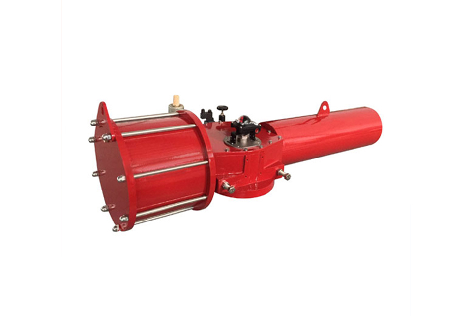
Assembly diagram and parts list of 67/68 pneumatic fork actuator
| Serial Number | Part Description | Material Standard |
|---|---|---|
| 1 | Cylinder Rear End Cover | QT500-7 |
|
2 3 |
Stud Bolt Cylinder Tie Rod |
C45 Alloy Steel |
| 4 | Cylinder Front End Cover | QT500-7 |
| 5 | Upper Cover | HT200 |
|
6 7 |
Cylinder Head (Body) Indicator Shaft |
QT500-7 C45 |
| 8 | Shaft Cover | HT200 |
| 9 | Indicator Plate | AL |
| 10 | O-ring | NBR |
| 11 | Sliding Bearing | H62 |
| 12 | O-ring | NBR |
| 13 | Roller Sleeve | GCr15 |
| 14 | Pin Shaft | GCr15 |
| 15 | Torsion Adjustment Indicator Rod | 45 |
| 16 | Worm | 45 |
| 17 | Labor-Saving Mechanism | / |
| 18 | Support Arm | 45 |
| 19 | Spring Seat Tie Rod | 45 |
| 20 | Spring Module | / |
| 21 | Hydraulic Module | / |
| 22 | Worm Gear Screw | C45 |
| 23 | Spring Seat | C45 |
| 24 | Right End Cover | Carbon Steel |
| 25 | Rear Pressure Cover | C45 |
| 26 | Guide Block | QT500-7 |
| 27 | O-ring | NBR |
| 28 | Fork Shaft | Carbon Steel |
| 29 | Box Body | Carbon Steel |
| 30 | Adjusting Bolt | C45-Ni |
| 31 | Wire Retaining Ring for Hole | 65Mn |
| 32 | Sliding Bearing | H62 |
| 33 | O-ring | NBR |
| 34 | Piston | Carbon Steel |
| 35 | O-ring | NBR |
| 36 | Guide Ring | PTFE |
| 37 | Cylinder Block | C20 |
| 38 | O-ring | NBR |
| 39 | Handwheel | DI |
67/68 Pneumatic Fork Operator Output Torque Table
Single acting torque output (metric unit: Nm)
*The biggest feature that distinguishes this actuator from other products is that its patented spring module can adjust the output torque appropriately.
| Gas source pressure model | 4 Bar | 5 Bar | 6 Bar | Spring reset torque | Optional manual device | ||||
|---|---|---|---|---|---|---|---|---|---|
| 0° Starting point | 90° End | 0° Starting point | 90° End | 0° Starting point | 90° End | 0° End | 90° Starting point | ||
| MN16-300 |
|
|
2194 | 1034 | 2972 | 1812 | 1700 | 2860 | Handwheel (HW) |
| MN16-350 | 2850 | 1690 | 3880 | 2720 |
|
|
1700 | 2860 | |
| MN25-350 |
|
|
3809 | 2383 | 5118 | 3692 | 2734 | 4160 | |
| MN25-450 | 4191 | 2765 | 5922 | 4496 |
|
|
2734 | 4160 | |
| MN30-500 |
|
|
9352 | 6551 | 12525 | 9724 | 6514 | 9315 | Manual hydraulic pump (HY) |
| MN30-550 | 9100 | 6300 | 12700 | 9900 |
|
|
5700 | 8500 | |
| MN35-550 |
|
|
14393 | 8751 | 18913 | 13271 | 8207 | 13849 | |
| MN35-600 | 13493 | 7851 | 18103 | 12461 |
|
|
8207 | 13849 | |
| MN35-700 | 21177 | 11174 | 29665 | 19669 | 38161 | 28157 | 12786 | 22789 | |
| MN40-800 | 35000 | 25600 | 47000 | 36000 |
|
|
18098 | 27523 | |
Double acting torque output of fork pneumatic actuator (metric unit: Nm)
| Gas source pressure model | 4Bar |
|
5Bar |
|
6Bar |
|
7Bar |
|
可选手动装置 |
|---|---|---|---|---|---|---|---|---|---|
| Start | Working | Start | Working | Start | Working | Start | Working | ||
| MN16-300 | 3115 | 1869 | 3894 | 2362 | - | - | - | - | 离合式手轮机构 |
| MN16-350 | 4550 | 2730 | - | - | - | - | - | - | |
| MN25-350 | 5235 | 3141 | 6543 | 3926 | 7852 | 4711 | - | - | 离合式手轮机构或手动液压泵(HY) |
| MN25-400 | 6925 | 4155 | 8656 | 5194 | 10388 | 6233 | - | - | |
| MN25-450 | 8412 | 5047 | 10515 | 6309 | 12618 | 7571 | - | - | 手动液压泵(HY) |
| MN30-450 | 10280 | 6168 | 12580 | 7548 | 15420 | 9252 | - | - | |
| MN30-500 | 12693 | 7616 | 15866 | 9520 | - | - | - | - | |
| MN30-550 | 14800 | 8880 | 18400 | 11040 | 22080 | 13248 | - | - | |
| MN35-550 | 18080 | 10848 | 22600 | 13560 | 27120 | 16272 | 31640 | 18984 | |
| MN35-600 | 21700 | 13020 | 26310 | 15786 | 31572 | 18943 | - | - | |
| MN35-500DA2 | 33964 | 24021 | 42455 | 30026 | 50946 | 36031 | 59437 | 42036 | |
| NM40-600DA2 | 59778 | 42276 | 74723 | 57095 | 89668 | 63414 | 104612 | 73984 |
Appearance dimensions of fork pneumatic actuator
| Model | D | L | L1 | L2 | H | E | E1 | E2 | D1 | H1 | B | T | D2 | N | M1 | M2 | X | Y | M3 |
单重KG DA/SR手动 |
手动 装置 |
|---|---|---|---|---|---|---|---|---|---|---|---|---|---|---|---|---|---|---|---|---|---|
| MN16-300 | 365 | 1628 | 513 | 688 | 107 | 75 | 130 | 280 | 80 | 150 | 22 | 82 | 165 | 4 | M20 | RC1/2 | 65 | 100 | M6 | 150/328 |
手轮 HW |
| MN16-350 | 415 | ||||||||||||||||||||
| MN25-350 | 415 | 1903 | 615 | 823 | 103 | 90 | 165 | 295 | 100 | 175 | 28 | 106 | 254 | 8 | M16 | RC1/2 | 65 | 100 | M6 | 340/480 |
手轮/ HW |
| MN25-400 | 465 | ||||||||||||||||||||
| MN25-450 | 515 | ||||||||||||||||||||
| MN30-450 | 515 | 2335 | 715 | 960 | 137 | 110 | 185 | 368 | 120 | 235 | 32 | 127 | 298 | 8 | M20 | RC3/4 | 70 | 140 | M8 |
400/ 825 |
手动 HY |
| MN30-500 | 585 | ||||||||||||||||||||
| MN30-550 | 620 | ||||||||||||||||||||
| MN35-550 | 620 | 2960 | 920 | 1230 | 155 | 143 | 220 | 453 | 160 | 261 | 40 | 169 | 356 | 8 | M30 | RC3/4 | 70 | 140 | M8 |
640/ 1400 |
手动 HY |
| MN35-600 | 685 | ||||||||||||||||||||
| MN35-700 | 750 |
Switching time and air consumption of fork pneumatic actuator
| Double action | Model | Cylinder diameter | Trip | Piston rod diameter | Single Trip Time (seconds) | Gas consumption (L/min) | Open (gas consumption L) | Off (gas consumption L) | One cycle gas consumption (L) |
|---|---|---|---|---|---|---|---|---|---|
| MN16-300DA | 300 | 179 | 32 | 20 | 155.6 | 14.06 | 11.22 | 15.28 | |
| MN16-350DA | 359 | 179 | 32 | 20 | 222.8 | 20.14 | 16.71 | 25.28 | |
| MN25-350DA | 359 | 214 | 38 | 20 | 266.4 | 23.68 | 19.65 | 43.33 | |
| MN25-400DA | 410 | 214 | 38 | 20 | 347.5 | 30.89 | 26.25 | 57.14 | |
| MN25-450DA | 450 | 214 | 38 | 20 | 418.6 | 37.21 | 32.11 | 69.32 | |
| MN30-450DA | 450 | 262 | 45 | 20 | 512.5 | 44.85 | 38.69 | 83.54 | |
| MN30-500DA | 500 | 262 | 45 | 20 | 632.7 | 55.37 | 48.5 | 103.87 | |
| MN30-550DA | 540 | 262 | 45 | 20 | 738 | 64.58 | 57.15 | 121.73 | |
| MN35-550DA | 540 | 342 | 55 | 20 | 963.4 | 82.9 | 73.37 | 156.27 | |
| MN35-600DA | 600 | 342 | 55 | 20 | 1189.3 | 102.35 | 91.72 | 194.07 | |
| MN35-700DA | 700 | 342 | 55 | 20 | 1618.8 | 139.31 | 126.66 | 266.17 |
| Single action | Model | Cylinder diameter | Trip | Piston rod diameter | Single Trip Time (seconds) | Gas consumption (L/min) | Open (gas consumption L) | One cycle gas consumption (L) |
|---|---|---|---|---|---|---|---|---|
| MN16-350-S4/5 | 359 | 179 | 32 | 20 | 222.8 | 16.71 | 16.71 | |
| MN25-400-S4/5 | 410 | 214 | 38 | 20 | 347.5 | 26.25 | 26.25 | |
| MN30-550-S4/5 | 540 | 262 | 45 | 20 | 738 | 57.15 | 57.15 | |
| MN35-600-S4/5 | 600 | 342 | 55 | 20 | 1189.3 | 91.72 | 91.72 | |
| MN16-300-S6 | 300 | 174 | 32 | 20 | 151.2 | 10.94 | 10.94 | |
| MN25-350-S5/6 | 359 | 214 | 38 | 20 | 266.4 | 19.65 | 19.65 | |
| MN30-500-S5/6 | 500 | 262 | 45 | 20 | 632.7 | 48.5 | 48.5 | |
| MN35-550-S5/6 | 540 | 342 | 55 | 20 | 963.4 | 73.37 | 73.37 |
Valve Installation & Maintenance
Valve Installation:
(1) Before installation, check that the product model, tag number, and specifications match the requirements. Inspect the entire valve for missing or loose parts.
(2) Prior to installation, clean the pipeline. Ensure there is sufficient straight pipe section at the valve inlet and install a filter. When connecting the valve body to the pipeline flanges, ensure coaxiality.
(3) Thoroughly clean the pipeline before installing the valve.
(4) The installation site should ensure the safety of personnel and equipment, facilitating operation, disassembly, and maintenance.
(5) The valve should be installed vertically upright on horizontal pipelines. If necessary, it can be installed at an angle, but horizontal installation should be avoided. For occasions with heavy valve weight or vibration, use a support frame.
(6) The medium flow direction must align with the arrow on the valve body. The air supply should be dry and oil-free. The valve should be used in environments with temperatures ranging from -20℃ to 55℃.
Valve Maintenance:
(1) Cleaning the Valve: For general media, cleaning with water is sufficient. For media harmful to health, first understand their properties and then select an appropriate cleaning method.
(2) Disassembly: Remove rust from exposed rusted parts first. Before derusting, protect the machined surfaces of precision parts such as the valve seat, valve plug, valve stem, and push rod. Use special tools when disassembling the valve seat.
(3) Valve Seat: Minor rust or wear on the sealing surface can be repaired by machining. If damage is severe, replace the seat. However, both repaired and replaced hard sealing surfaces must be lapped.
(4) Valve Stem: If the surface is damaged, it must be replaced.
(5) Damage to Push Rod, Guide, and Sealing Surfaces: Reverse-acting actuators must be replaced; direct-acting actuators can be reused after proper repair.
(6) Compression Spring: If there are cracks or other defects affecting strength, replace it immediately.
(7) Wear Parts: Packing, gaskets, and O-rings must be replaced entirely during each maintenance. Check the valve plug and diaphragm for cracks, aging, or corrosion that may cause future failures. Decide whether to replace them based on inspection results, but the diaphragm service life should not exceed 2-3 years.
(8) When reassembling the valve, ensure alignment. Tighten bolts diagonally and lubricate sliding parts. After reassembly, debug the valve according to the factory test items and methods. During this period, accurately adjust the packing compression force and the valve plug closing position.
Ordering Instructions
When placing an order, please fill in the Specification Sheet or specify the following information:
-
If the model has not been selected before ordering, please provide us with the operating parameters:
(1) Nominal diameter DN (mm);
(2) Nominal pressure (MPa or bar);
(3) Fluid properties (including medium temperature, viscosity, or acidity/alkalinity);
(4) Pressure before and after the valve (pressure differential);
(5) Requirements for flow characteristics;
(6) Materials of valve body and valve core;
(7) Connection type;
(8) Driving method (provide air supply pressure, driving voltage);
(9) Supporting accessories (for pneumatic valves, it is recommended that users install an air filter triplet and a 2-position 5-way solenoid valve);
(10) On-site working conditions. -
If the product model of our company has been selected by the design unit, please order directly from our production department according to the model;
-
When the application occasion is very important or the pipeline is relatively complex, please provide the design drawings and detailed parameters as much as possible, and our experts will review and check them for you.


