


Introduction
2.1 Housing
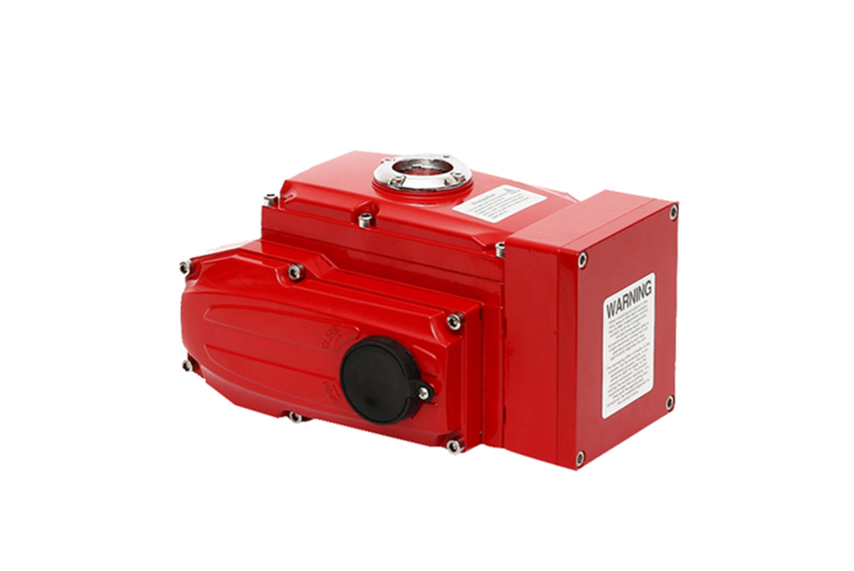
The housing is made of hard aluminum alloy, treated with anodizing and polyester powder coating, featuring strong corrosion resistance. It has a protection rating of IP67, NEMA 4 and 6, with an IP68 version available as an option.
The housing is made of hard aluminum alloy, treated with anodizing and polyester powder coating, featuring strong corrosion resistance. It has a protection rating of IP67, NEMA 4 and 6, with an IP68 version available as an option.
2.2 Motor
A fully enclosed squirrel-cage motor with small size, large torque, and low inertia. It has an insulation class of F and a built-in overheat protection switch to prevent damage from overheating.
A fully enclosed squirrel-cage motor with small size, large torque, and low inertia. It has an insulation class of F and a built-in overheat protection switch to prevent damage from overheating.
2.3 Manual Structure
The handle is designed for safe, reliable, labor-saving operation with a compact size. When power is off, the handle can be toggled for manual operation. When manual operation is not needed, the wrench can be placed in the wrench holder for convenient use.
The handle is designed for safe, reliable, labor-saving operation with a compact size. When power is off, the handle can be toggled for manual operation. When manual operation is not needed, the wrench can be placed in the wrench holder for convenient use.
2.4 Indicator
The indicator is mounted on the central shaft for observing the valve position. The lens adopts a convex design to prevent water accumulation, ensuring convenient observation.
The indicator is mounted on the central shaft for observing the valve position. The lens adopts a convex design to prevent water accumulation, ensuring convenient observation.
2.5 Dryer
Used to control temperature, preventing internal moisture condensation in the actuator caused by temperature and weather changes, thus keeping internal electrical components dry.
Used to control temperature, preventing internal moisture condensation in the actuator caused by temperature and weather changes, thus keeping internal electrical components dry.
2.6 Sealing
It has excellent sealing performance. The standard product has a protection rating of IP67, with an optional IP68 protection rating.
It has excellent sealing performance. The standard product has a protection rating of IP67, with an optional IP68 protection rating.
2.7 Limit Switch
Equipped with dual mechanical and electronic limits. The mechanical limit screws are adjustable for safe and reliable operation; the electronic limit switch is controlled by a cam mechanism, with a simple adjustment structure enabling precise and convenient position setting, and it is not affected by excessive rotation of the handwheel.
Equipped with dual mechanical and electronic limits. The mechanical limit screws are adjustable for safe and reliable operation; the electronic limit switch is controlled by a cam mechanism, with a simple adjustment structure enabling precise and convenient position setting, and it is not affected by excessive rotation of the handwheel.
2.8 Self-Locking
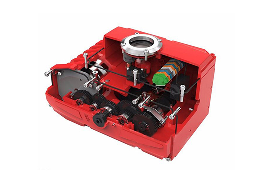
A precision worm and worm gear mechanism enables efficient transmission of large torque, with high efficiency, low noise (maximum 50 dB), and long service life. It has a self-locking function to prevent reverse rotation, ensuring stable and reliable operation of transmission parts, and no additional lubrication is required.
A precision worm and worm gear mechanism enables efficient transmission of large torque, with high efficiency, low noise (maximum 50 dB), and long service life. It has a self-locking function to prevent reverse rotation, ensuring stable and reliable operation of transmission parts, and no additional lubrication is required.
2.9 Anti-Drop Bolts
When the housing is removed, bolts remain attached to the shell and will not fall off.
When the housing is removed, bolts remain attached to the shell and will not fall off.
2.10 Installation
The bottom mounting dimensions comply with ISO5211/ DIN3337 international standards. The holes are in a double square shape, facilitating linear or 45° angle installation of valves with square stems, offering strong adaptability. It can be installed either vertically or horizontally.
The bottom mounting dimensions comply with ISO5211/ DIN3337 international standards. The holes are in a double square shape, facilitating linear or 45° angle installation of valves with square stems, offering strong adaptability. It can be installed either vertically or horizontally.
2.11 Wiring
Control circuits comply with single-phase or three-phase power standards, with compact and reasonable wiring arrangement. Terminal blocks can effectively meet the requirements of various additional functions.
Control circuits comply with single-phase or three-phase power standards, with compact and reasonable wiring arrangement. Terminal blocks can effectively meet the requirements of various additional functions.
Technical Parameter
Main technical parameters
| Model | Maximum output torque | 90 ° action time | Output shaft | Electrical machinery | Single phase rated current | Weight | |
|---|---|---|---|---|---|---|---|
| Square | Round | ||||||
| N·M | S | mm | W | 220V | Kg | ||
| MS-005 | 50 | 30 | 11×11 | Φ12.6 | 10 | 0.25 | 3.6 |
| 14×14 | |||||||
| MS-008 | 80 | 30 | 11×11 | Φ15.7 | 10 | 0.25 | 3.6 |
| 14×14 | |||||||
| MS-010 | 100 | 30 | 14×14 | Φ15.7 | 15 | 0.35 | 4.6 |
| 17×17 | Φ18.95 | ||||||
| MS-015 | 150 | 30 | 14×14 | Φ18.95 | 15 | 0.37 | 4.6 |
| 17×17 | |||||||
| MS-020 | 200 | 30 | 22×22 | Φ22.13 | 45 | 0.3 | 13 |
| MS-030 | 300 | 30 | 22×22 | Φ28.48 | 45 | 0.31 | 13.4 |
| MS-040 | 400 | 30 | 22×22 | Φ28.48 | 60 | 0.33 | 13.8 |
| MS-060 | 600 | 30 | 27×27 | Φ31.65 | 90 | 0.33 | 14 |
| MS-080 | 800 | 45 | 27×27 | Φ31.65 | 180 | 0.47 | 14.3 |
| MS-100 | 1000 | 135 | 27×27 | Φ31.65 | 180 | 0.47 | 60 |
| MS-160 | 1600 | 135 | Max φ65 | 180 | 0.85 | 60 | |
| MS-200 | 2000 | 135 | Max φ65 | 180 | 0.85 | 60 | |
| MS-300 | 3000 | 135 | Max φ65 | 180 | 0.85 | 60 | |
Technical parameters of standard parts
| Enclosure | Waterproof rating: IP67, NEMA 4 and 6 |
| Motor power supply | 110/220V AC single-phase, 380/440V AC three-phase, 50/60Hz, ±10% |
| Control power supply | 110/220V AC single-phase, 50/60 Hz, ±10% |
| Control signal | Input and output: 4 - 20mA |
| Motor | Squirrel-cage asynchronous motor |
| Limit switch | 2 x Open/Close, SPDT, 250V AC 10A |
| Auxiliary limit switch | 2 x Open/Close, SPDT, 250V AC 10A |
| Stroke | 90° ± 10° (180°/270° optional) |
| Fail-safe/Operating temperature | Built-in overheat protection, On: 120℃ ± 5℃ / Off: 97℃ ± 5℃ |
| Indicator | Continuous position indication |
| Manual operation | Mechanical handle |
| Self-locking device | Worm gear and worm mechanism provide self-locking |
| Mechanical limit | 2 external adjustment bolts |
| Dryer | 7 - 10W (110/220V AC) for anti-condensation |
| Wiring holes | 2 x M18 |
| Ambient temperature | -20℃ - +70℃ |
| Lubrication | Aluminum-based grease (EP type) |
Valve Installation & Maintenance
Valve Installation:
(1) Before installation, check that the product model, tag number, and specifications match the requirements. Inspect the entire valve for missing or loose parts.
(2) Prior to installation, clean the pipeline. Ensure there is sufficient straight pipe section at the valve inlet and install a filter. When connecting the valve body to the pipeline flanges, ensure coaxiality.
(3) Thoroughly clean the pipeline before installing the valve.
(4) The installation site should ensure the safety of personnel and equipment, facilitating operation, disassembly, and maintenance.
(5) The valve should be installed vertically upright on horizontal pipelines. If necessary, it can be installed at an angle, but horizontal installation should be avoided. For occasions with heavy valve weight or vibration, use a support frame.
(6) The medium flow direction must align with the arrow on the valve body. The air supply should be dry and oil-free. The valve should be used in environments with temperatures ranging from -20℃ to 55℃.
Valve Maintenance:
(1) Cleaning the Valve: For general media, cleaning with water is sufficient. For media harmful to health, first understand their properties and then select an appropriate cleaning method.
(2) Disassembly: Remove rust from exposed rusted parts first. Before derusting, protect the machined surfaces of precision parts such as the valve seat, valve plug, valve stem, and push rod. Use special tools when disassembling the valve seat.
(3) Valve Seat: Minor rust or wear on the sealing surface can be repaired by machining. If damage is severe, replace the seat. However, both repaired and replaced hard sealing surfaces must be lapped.
(4) Valve Stem: If the surface is damaged, it must be replaced.
(5) Damage to Push Rod, Guide, and Sealing Surfaces: Reverse-acting actuators must be replaced; direct-acting actuators can be reused after proper repair.
(6) Compression Spring: If there are cracks or other defects affecting strength, replace it immediately.
(7) Wear Parts: Packing, gaskets, and O-rings must be replaced entirely during each maintenance. Check the valve plug and diaphragm for cracks, aging, or corrosion that may cause future failures. Decide whether to replace them based on inspection results, but the diaphragm service life should not exceed 2-3 years.
(8) When reassembling the valve, ensure alignment. Tighten bolts diagonally and lubricate sliding parts. After reassembly, debug the valve according to the factory test items and methods. During this period, accurately adjust the packing compression force and the valve plug closing position.
Ordering Instructions
When placing an order, please fill in the Specification Sheet or specify the following information:
-
If the model has not been selected before ordering, please provide us with the operating parameters:
(1) Nominal diameter DN (mm);
(2) Nominal pressure (MPa or bar);
(3) Fluid properties (including medium temperature, viscosity, or acidity/alkalinity);
(4) Pressure before and after the valve (pressure differential);
(5) Requirements for flow characteristics;
(6) Materials of valve body and valve core;
(7) Connection type;
(8) Driving method (provide air supply pressure, driving voltage);
(9) Supporting accessories (for pneumatic valves, it is recommended that users install an air filter triplet and a 2-position 5-way solenoid valve);
(10) On-site working conditions. -
If the product model of our company has been selected by the design unit, please order directly from our production department according to the model;
-
When the application occasion is very important or the pipeline is relatively complex, please provide the design drawings and detailed parameters as much as possible, and our experts will review and check them for you.


