


Introduction
-
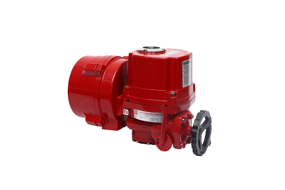
Housing—Made of high-quality aluminum alloy, it is lightweight. Both the inner and outer surfaces undergo anodizing treatment, and the outer surface is coated with polyester powder, ensuring strong corrosion resistance.
-
Motor—Adopts a squirrel-cage motor with large output torque. It is equipped with a built-in thermal protection switch for temperature control to prevent motor damage.
-
Manual Structure—When power is off, the clutch handle can be pulled for manual operation. When power is on, the clutch automatically resets.
-
Position Indicator—Installed on the central shaft, it allows observation of the valve position. An indicator light (SLU) is also available as an option.
-
Dryer—Used to control temperature, prevent moisture condensation inside the actuator, and keep internal electrical components dry.
-
Limit Switch—Controlled by a cam mechanism, the simple adjustment structure enables precise and convenient position setting.
-
Torque Switch (except HQ-008)—Provides overload protection to prevent motor damage. (Pre-set before leaving the factory; users are not advised to modify the settings arbitrarily.)
-
Self-locking—Features a self-locking function to prevent reverse rotation, ensuring stable and reliable operation of rotating parts.
-
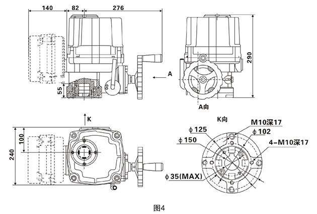
Installation—The bottom mounting dimensions comply with the ISO5211 international standard. The drive sleeve can be disassembled and processed as needed, offering strong adaptability. It can be installed either vertically or horizontally.
-
Terminal Blocks—Wiring is compact and reasonably arranged. The terminal blocks have a diameter of 2.5mm, ensuring high pressure and firm connections.
-
Worm Gear—Adopts a concave wheel design, with a large contact area with the worm. It transmits large torque, operates stably, is wear-resistant, and has a long service life.
Technical Parameter
Technical Parameter
| Model | Maximum output torque | Action time 60/50Hz | Maximum shaft diameter | Motor Class F | Rated current (A) 50HZ | Hand wheel speed | Weight | |||
|---|---|---|---|---|---|---|---|---|---|---|
| Single phase | Three-phase | |||||||||
| N·M | 90° | mm | W | 110V | 220V | 380V | 440V | N | kg | |
| OHQ-005 | 50 | 18/22 | Ф20 | 20 | 1.10/0.95 | 0.55/0.54 | 0.3/0.3 | N/A | 10 | 7.5 |
| OHQ-008 | 80 | 18/22 | Ф20 | 20 | 1.10/0.95 | 0.55/0.54 | 0.3/0.3 | N/A | 10 | 7.5 |
| OHQ-010 | 100 | 18/22 | Ф20 | 20 | 1.10/0.95 | 0.55/0.54 | 0.3/0.3 | N/A | 10 | 7.5 |
| OHQ-015 | 150 | 21/25 | Ф22 | 40 | 1.65/1.67 | 0.88/0.84 | 0.31/0.31 | 0.30/0.31 | 11 | 17.3 |
| OHQ-020 | 200 | 21/25 | Ф22 | 40 | 1.67/1.67 | 0.89/0.85 | 0.31/0.31 | 0.30/0.31 | 11 | 17.3 |
| OHQ-030 | 300 | 26/31 | Ф35 | 90 | 1.85/1.86 | 0.92/0.92 | 0.35/0.35 | 0.34/0.34 | 13.5 | 22 |
| OHQ-050 | 500 | 26/31 | Ф35 | 90 | 3.60/3.62 | 1.55/1.58 | 0.59/0.59 | 0.58/0.58 | 13.5 | 23 |
| OHQ-060 | 600 | 26/31 | Ф35 | 120 | 3.65/3.62 | 1.60/2.20 | 0.60/0.59 | 0.59/0.58 | 13.5 | 23 |
| OHQ-080 | 800 | 31/37 | Ф45 | 180 | 4.10/4.10 | 2.15/2.20 | 0.85/0.85 | 0.79/0.79 | 16.5 | 29 |
| OHQ-120 | 1200 | 31/37 | Ф45 | 180 | 4.20/4.10 | 2.35/2.30 | 0.87/0.87 | 0.81/0.81 | 16.5 | 29 |
| OHQ-200 | 2000 | 93/112 | Ф65 | 180 | 4.10/4.10 | 2.15/2.20 | 0.85/0.85 | 0.79/0.79 | 49.5 | 75 |
Standard Parameters
| Casing | Aluminum alloy shell, waterproof level: IP67, NEMA4 and 6 |
|
| Motor power supply | 110/220V AC, 1 Phase; 380/440V AC, 3 Phase; 50/60HZ,±10% |
|
| Control power supply | 110/220V AC, 1 Phase; 50/60HZ,±10% |
|
| Electrical machinery | Squirrel cage induction motors |
|
| Limit switch | SPDT, 250V AC, 10A | OHQ-005/008/010除外 |
| Auxiliary limit switch | SPDT, 250V AC, 10A |
|
| Trip | 90°-270±10° (Advanced explanation for temperatures above 90 °) | 0°-270° |
| Failure protection/operating temperature | Built in thermal protection on: 120°C±5°C关:97°C±15°C |
|
| Indicator | Continuous position indication |
|
| Manual operation | Mechanical handle (optional handwheel) |
|
| Self-lock device | Turbine and worm mechanism provide self-locking |
|
| Mechanical limit | 2 external adjustments |
|
| Wiring hole | M18 (2个) |
|
| Ambient temperature | -20°C ~+70°C |
|
| lubrication | Aluminum based grease (EP type) |
|
| Material | Steel, aluminum alloy, aluminum bronze, polycarbonate |
|
| Ambient humidity | Maximum 90% RH | Non-condensing |
| Seismic performance | X Y Z 10g, 0.2~34HZ, 30 points |
|

Valve Installation & Maintenance
Valve Installation:
(1) Before installation, check that the product model, tag number, and specifications match the requirements. Inspect the entire valve for missing or loose parts.
(2) Prior to installation, clean the pipeline. Ensure there is sufficient straight pipe section at the valve inlet and install a filter. When connecting the valve body to the pipeline flanges, ensure coaxiality.
(3) Thoroughly clean the pipeline before installing the valve.
(4) The installation site should ensure the safety of personnel and equipment, facilitating operation, disassembly, and maintenance.
(5) The valve should be installed vertically upright on horizontal pipelines. If necessary, it can be installed at an angle, but horizontal installation should be avoided. For occasions with heavy valve weight or vibration, use a support frame.
(6) The medium flow direction must align with the arrow on the valve body. The air supply should be dry and oil-free. The valve should be used in environments with temperatures ranging from -20℃ to 55℃.
Valve Maintenance:
(1) Cleaning the Valve: For general media, cleaning with water is sufficient. For media harmful to health, first understand their properties and then select an appropriate cleaning method.
(2) Disassembly: Remove rust from exposed rusted parts first. Before derusting, protect the machined surfaces of precision parts such as the valve seat, valve plug, valve stem, and push rod. Use special tools when disassembling the valve seat.
(3) Valve Seat: Minor rust or wear on the sealing surface can be repaired by machining. If damage is severe, replace the seat. However, both repaired and replaced hard sealing surfaces must be lapped.
(4) Valve Stem: If the surface is damaged, it must be replaced.
(5) Damage to Push Rod, Guide, and Sealing Surfaces: Reverse-acting actuators must be replaced; direct-acting actuators can be reused after proper repair.
(6) Compression Spring: If there are cracks or other defects affecting strength, replace it immediately.
(7) Wear Parts: Packing, gaskets, and O-rings must be replaced entirely during each maintenance. Check the valve plug and diaphragm for cracks, aging, or corrosion that may cause future failures. Decide whether to replace them based on inspection results, but the diaphragm service life should not exceed 2-3 years.
(8) When reassembling the valve, ensure alignment. Tighten bolts diagonally and lubricate sliding parts. After reassembly, debug the valve according to the factory test items and methods. During this period, accurately adjust the packing compression force and the valve plug closing position.
Ordering Instructions
When placing an order, please fill in the Specification Sheet or specify the following information:
-
If the model has not been selected before ordering, please provide us with the operating parameters:
(1) Nominal diameter DN (mm);
(2) Nominal pressure (MPa or bar);
(3) Fluid properties (including medium temperature, viscosity, or acidity/alkalinity);
(4) Pressure before and after the valve (pressure differential);
(5) Requirements for flow characteristics;
(6) Materials of valve body and valve core;
(7) Connection type;
(8) Driving method (provide air supply pressure, driving voltage);
(9) Supporting accessories (for pneumatic valves, it is recommended that users install an air filter triplet and a 2-position 5-way solenoid valve);
(10) On-site working conditions. -
If the product model of our company has been selected by the design unit, please order directly from our production department according to the model;
-
When the application occasion is very important or the pipeline is relatively complex, please provide the design drawings and detailed parameters as much as possible, and our experts will review and check them for you.


