


Characteristic
- User friendly, one click local interface
- Non contact, electromagnetic sensor
- Optional integrated magnetic feedback
- Industrial aluminum casing
- Universal design suitable for both straight and angular travel
- Universal labels with FM, FMc, ATEX, IEC, CE certification
- Compatible with HART communication protocol
- Built in independent solid-state valve position switch
- Support eDDL and DTM
Benefit
- Quickly adjust and initialize the regulating valve
- Improve valve performance and reliability
- Bidirectional communication meets the requirements of local and remote settings
- Can be integrated with multiple control systems and asset management software
Technical Introduction
Specifications
Shell:
• Shell/Cover: Low copper alumina, compliant with ASTM 360 standard
• Coating: Apply gray polyurethane (RAL 7001) on top of epoxy primer
• Protection standards: Compliant with IP66 and NEMA 4X standards
Weight: 2 kg (4.5 lb)
Input power and signal: Minimum/maximum current: 3.2 mA/24 mA
• Terminal voltage: 9 Vdc@20 mA
• Wiring terminals:
Threaded crimping
• Electrical connections:
Single 1/2NPT internal thread connection
Output signal:
Two configurable solid-state switches 1A 30Vdc, normally open or normally off setting
Communication, setup, and calibration:
Local buttons and LED displays are used for setting and tuning, including valve zero point, full range, mode of action, automatic tuning, and related parameter settings
• HART protocol, (REV. 5)
Environmental temperature and humidity limitations:
40 to 85 C (-40 to 185 F)
10% to 95% relative humidity (RH), non condensing
Compatible with tropical environments
• Meets the ASTM-G21 standard for mold and bacteria resistance
Apply anti mold coating on exposed circuits
Positive pressure shell with insect proof sieve holes
EMC compatibility standards:
• EN 61000-4-2, 3, 5, 6, 8- EMC 89/336/EEC Directive
• IEC 801-2、-3、-4
• CE mark: Complies with ATEX 94/9/EC and EMC 2004/108/EC standards
Performance complies with ISA S75.13 1996 standard:
Accuracy:+/-0.5% of full scale
Hysteresis+Dead Zone:+/-0.3% of full scale
Repeatability:+/-0.3% of full scale,
Start time<500 ms,
Instant power loss with no impact<100 ms
Options:
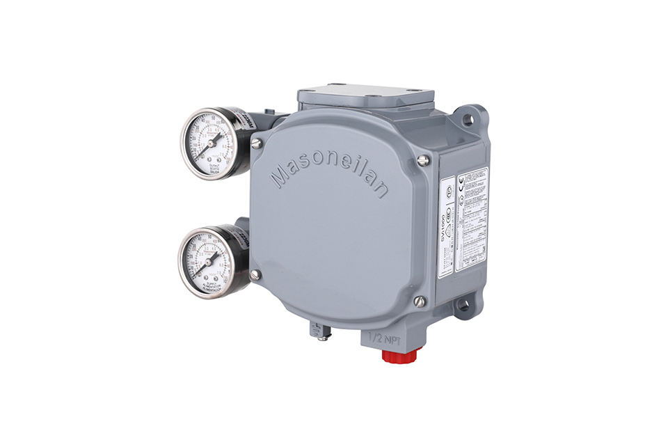
/G (input and output pressure gauge),/IM (integrated magnetic feedback),
/SW (Solid State Switch),
Execution mechanism performance:
• Scope of application for non-contact magnetic feedback:
Attachment
(1) Before installation, check that the product model, tag number, and specifications match the requirements. Inspect the entire valve for missing or loose parts.
(2) Prior to installation, clean the pipeline. Ensure there is sufficient straight pipe section at the valve inlet and install a filter. When connecting the valve body to the pipeline flanges, ensure coaxiality.
(3) Thoroughly clean the pipeline before installing the valve.
(4) The installation site should ensure the safety of personnel and equipment, facilitating operation, disassembly, and maintenance.
(5) The valve should be installed vertically upright on horizontal pipelines. If necessary, it can be installed at an angle, but horizontal installation should be avoided. For occasions with heavy valve weight or vibration, use a support frame.
(6) The medium flow direction must align with the arrow on the valve body. The air supply should be dry and oil-free. The valve should be used in environments with temperatures ranging from -20℃ to 55℃.
(1) Cleaning the Valve: For general media, cleaning with water is sufficient. For media harmful to health, first understand their properties and then select an appropriate cleaning method.
(2) Disassembly: Remove rust from exposed rusted parts first. Before derusting, protect the machined surfaces of precision parts such as the valve seat, valve plug, valve stem, and push rod. Use special tools when disassembling the valve seat.
(3) Valve Seat: Minor rust or wear on the sealing surface can be repaired by machining. If damage is severe, replace the seat. However, both repaired and replaced hard sealing surfaces must be lapped.
(4) Valve Stem: If the surface is damaged, it must be replaced.
(5) Damage to Push Rod, Guide, and Sealing Surfaces: Reverse-acting actuators must be replaced; direct-acting actuators can be reused after proper repair.
(6) Compression Spring: If there are cracks or other defects affecting strength, replace it immediately.
(7) Wear Parts: Packing, gaskets, and O-rings must be replaced entirely during each maintenance. Check the valve plug and diaphragm for cracks, aging, or corrosion that may cause future failures. Decide whether to replace them based on inspection results, but the diaphragm service life should not exceed 2-3 years.
(8) When reassembling the valve, ensure alignment. Tighten bolts diagonally and lubricate sliding parts. After reassembly, debug the valve according to the factory test items and methods. During this period, accurately adjust the packing compression force and the valve plug closing position.
-
If the model has not been selected before ordering, please provide us with the operating parameters:
(1) Nominal diameter DN (mm);
(2) Nominal pressure (MPa or bar);
(3) Fluid properties (including medium temperature, viscosity, or acidity/alkalinity);
(4) Pressure before and after the valve (pressure differential);
(5) Requirements for flow characteristics;
(6) Materials of valve body and valve core;
(7) Connection type;
(8) Driving method (provide air supply pressure, driving voltage);
(9) Supporting accessories (for pneumatic valves, it is recommended that users install an air filter triplet and a 2-position 5-way solenoid valve);
(10) On-site working conditions. -
If the product model of our company has been selected by the design unit, please order directly from our production department according to the model;
-
When the application occasion is very important or the pipeline is relatively complex, please provide the design drawings and detailed parameters as much as possible, and our experts will review and check them for you.


