


Technical Parameter
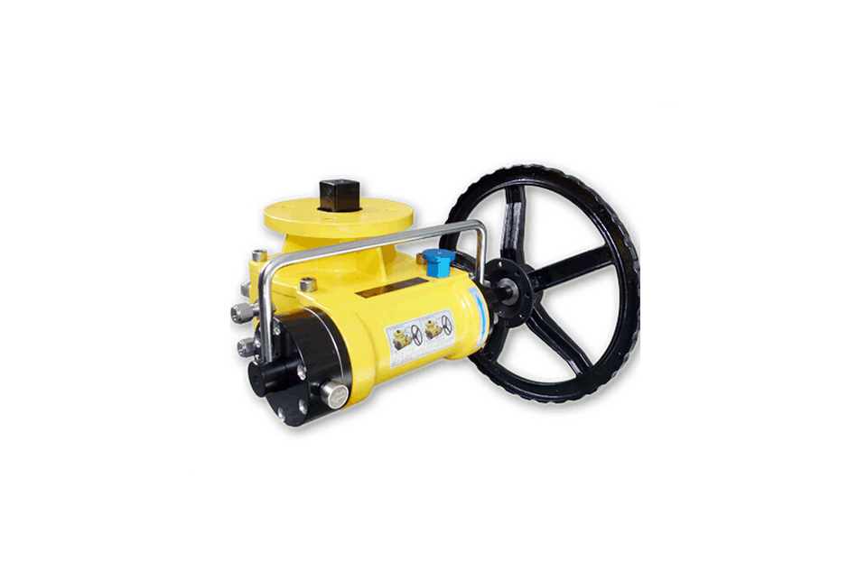
Dimension diagram and torque output table of clutch handwheel operating mechanism
| Model | A | B | C | D1 | D2 | D3 D4 D5 | E | L | M1 | M2 | T1 | T2 | H1 | H2 | K | J | Recommended actuator model | Input torque | Output torque |
|---|---|---|---|---|---|---|---|---|---|---|---|---|---|---|---|---|---|---|---|
| DFM-015A | 120 | 100 | 104 | Φ50 | Φ70 | F05.F07 | 44.5 | 114 | Φ7 | 4-Φ9 | □17 | □17 | 14 | 25 | Φ160 | 1/4"NPT | DFS032-085 | 17Nm | 150Nm |
| DFM-015B | 120 | 100 | 104 | Φ50 | Φ70 | F05.F07 | 44.5 | 120 | Φ7 | 4-Φ9 | □17 | □17 | 14 | 25 | Φ200 | 1/4"NPT | DFS075-100 | 22Nm | 200Nm |
| DFM-060 | 192 | 148 | 145 | Φ70 | Φ102 | F07.F10 | 71 | 175 | Φ9 | 4-Φ11 | □22 | □22 | 19 | 30 | Φ200 | 1/4"NPT | DFS100-145 | 42Nm | 600Nm |
| DFM-090A | 192 | 148 | 145 | Φ70 | Φ102 | F07.F10.F12 | 71 | 178 | Φ9 | 4-Φ11 | □27 | □27 | 19 | 30 | Φ250 | 1/4"NPT | DFS145-160 | 70Nm | 900Nm |
| DFM-090B | 192 | 148 | 145 | Φ70 | Φ102 | F07.F10.F12 | 71 | 181 | Φ9 | 4-Φ11 | □27 | □27 | 19 | 30 | Φ300 | 1/4"NPT | DFS145-180 | 96Nm | 1200Nm |
| DFM-160A | 260 | 196 | 191.5 | Φ102 | Φ125 | F10.F12 | 107.5 | 268 | Φ11 | 4-Φ13 | □36 | □36 | 34 | 40 | Φ350 | 1/4"NPT | DFS160-200 | 80Nm | 1600Nm |
| DFM-160B | 260 | 196 | 191.5 | Φ102 | Φ125 | F10.F12 | 107.5 | 272 | Φ11 | 4-Φ13 | □36 | □36 | 34 | 40 | Φ400 | 1/4"NPT | DFS200-240 | 100Nm | 2000Nm |
| DFM-350A | 334 | 255 | 181 | Φ165 | * | F12.F16 | 123 | 272 | Φ22 | * | □46 | □46 | 45 | 176 | Φ600 | 1/4"NPT | DFS240-265 | 190Nm | 3300Nm |
| DFM-350B | 334 | 255 | 181 | Φ165 | * | F12.F16 | 123 | 275 | Φ22 | * | □46 | □46 | 45 | 176 | Φ700 | 1/4"NPT | DFS265-300 | 230Nm | 4000Nm |
| DFM-700 | 389 | 297 | 249 | Φ165 | Φ254 | F16.F25 | 156 | 418 | Φ22 | 8-Φ13 | □46 | □46 | 45 | 196 | Φ500 | 1/2"NPT | DFS350-400 | 110Nm | 7000Nm |
1.The value F12 under D3.D4.D5 in the DFM-090A/B column is optional.
2.The appearance and installation dimensions of the clutch series (conventional type) and the safety switching series are exactly the same.
Parts List
| NO. | Name | Quantity | Material |
|---|---|---|---|
| 1 | Worm gear box | 1 | WCB |
| 2 | Adjust bolt components | 2 | 304 |
| 3 | O-ring (under shaft) | 1 | NBR |
| 4 | Bearing (under shaft) | 1 | PCM |
| 5 | Bearing (under shaft) | 1 | PCM |
| 6 | Limit component | 1 | 45 |
| 7 | Output shaft | 1 | 45 |
| 8 | Gasket (on shaft) | 1 | POM |
| 9 | Bearing (on shaft) | 1 | POM |
| 10 | O-ring (on shaft) | 1 | NBR |
| 11 | O-ring (box cover) | 1 | NBR |
| 12 | Tank cover | 1 | WCB |
| 13 | Box cover screws | 4 | 304 |
| 14 | Left cover screw | 6 | 304 |
| 15 | Left end cover | 1 | 45 |
| *15A | Gas source switching valve | 1 | 45 |
| *16 | Left end cover | 1 | AL380 |
| 17 | O-ring (left and right end caps) | 2 | NBR |
| 18 | O-ring (small end of left eccentric shaft) | 1 | NBR |
| 19 | O-ring (eccentric shaft) | 2 | NBR |
| 20 | Eccentric shaft bearing | 2 | POM |
| 21 | Hexagon socket set screws with cone point | 1 | 304 |
| 22 | Left eccentric half shaft | 1 | 45 |
| 23 | Worm shaft sleeve | 2 | Cu |
| 24 | Thrust ball bearing | 2 | Steel |
| 25 | Worm | 1 | 45 |
| 26 | Right eccentric half shaft | 1 | 45 |
| 27 | Round handle | 1 | 45 |
| 28 | O-ring (eccentric shaft) | 1 | NBR |
| 29 | Right end cover | 1 | 45 |
| 30 | Right cover screw | 6 | 304 |
| 31 | Handwheel | 1 | 20 |
| 32 | Flat washer | 1 | 20 |
| 33 | Bolt | 1 | 304 |
| *34 | Lock plate | 1 | 45 |
| *35 | Lock frame | 1 | 45 |
Note: Parts marked with an asterisk (*) are selected components
Single weight and packaging size
| Model | Single weight (KG) | Internal dimensions (CM) | Notes | |
|---|---|---|---|---|
| DFM-15A | 5.1 | 21*15*12 | Handwheel body (with exhaust valve) | |
| DFM-15B | 5.1 | 21*15*12 | ||
| DFM-60 | 16.1 | 31*22*17 | ||
| DFM-90A | 16.5 | 31*22*18 | ||
| DFM-90B | 16.8 | 31*22*18 | ||
| DFM-160A | 32 | 43*31*24 | ||
| DFM-160B | 33 | 43*31*24 | ||
| DFM-350A | 46 | 43*36*19 | ||
| DFM-350B | 48.5 | 43*36*19 | ||
| DFM-700 | 121 |
|
||
| φ160 | 0.6 | 20.5*20.5*4.5 | 15-A | Wheel |
| φ200 (Small hole) | 0.6 | 20.5*20.5*4.5 | 15-B | |
| φ200 (Large hole) | 0.6 | 20.5*20.5*4.5 | 60 | |
| φ250 | 0.9 | 25.5*25.5*4 | 90-A | |
| φ300 | 1.3 | 30.5*30.5*5 | 90-B | |
| φ350 | 1.9 | 35.5*35.5*7 | 160-A | |
| φ400 | 2.7 | 40.5*40.5*7 | 160-B | |
| φ500 | 4.1 | 51*51*7 | 350-A | |
| φ600 | 5 | 61*61*7 | 350-A | |
| φ700 | 6.2 | 71*71*14.5 |
350-B |
|
Valve Installation & Maintenance
Valve Installation:
(1) Before installation, check that the product model, tag number, and specifications match the requirements. Inspect the entire valve for missing or loose parts.
(2) Prior to installation, clean the pipeline. Ensure there is sufficient straight pipe section at the valve inlet and install a filter. When connecting the valve body to the pipeline flanges, ensure coaxiality.
(3) Thoroughly clean the pipeline before installing the valve.
(4) The installation site should ensure the safety of personnel and equipment, facilitating operation, disassembly, and maintenance.
(5) The valve should be installed vertically upright on horizontal pipelines. If necessary, it can be installed at an angle, but horizontal installation should be avoided. For occasions with heavy valve weight or vibration, use a support frame.
(6) The medium flow direction must align with the arrow on the valve body. The air supply should be dry and oil-free. The valve should be used in environments with temperatures ranging from -20℃ to 55℃.
Valve Maintenance:
(1) Cleaning the Valve: For general media, cleaning with water is sufficient. For media harmful to health, first understand their properties and then select an appropriate cleaning method.
(2) Disassembly: Remove rust from exposed rusted parts first. Before derusting, protect the machined surfaces of precision parts such as the valve seat, valve plug, valve stem, and push rod. Use special tools when disassembling the valve seat.
(3) Valve Seat: Minor rust or wear on the sealing surface can be repaired by machining. If damage is severe, replace the seat. However, both repaired and replaced hard sealing surfaces must be lapped.
(4) Valve Stem: If the surface is damaged, it must be replaced.
(5) Damage to Push Rod, Guide, and Sealing Surfaces: Reverse-acting actuators must be replaced; direct-acting actuators can be reused after proper repair.
(6) Compression Spring: If there are cracks or other defects affecting strength, replace it immediately.
(7) Wear Parts: Packing, gaskets, and O-rings must be replaced entirely during each maintenance. Check the valve plug and diaphragm for cracks, aging, or corrosion that may cause future failures. Decide whether to replace them based on inspection results, but the diaphragm service life should not exceed 2-3 years.
(8) When reassembling the valve, ensure alignment. Tighten bolts diagonally and lubricate sliding parts. After reassembly, debug the valve according to the factory test items and methods. During this period, accurately adjust the packing compression force and the valve plug closing position.
Ordering Instructions
When placing an order, please fill in the Specification Sheet or specify the following information:
-
If the model has not been selected before ordering, please provide us with the operating parameters:
(1) Nominal diameter DN (mm);
(2) Nominal pressure (MPa or bar);
(3) Fluid properties (including medium temperature, viscosity, or acidity/alkalinity);
(4) Pressure before and after the valve (pressure differential);
(5) Requirements for flow characteristics;
(6) Materials of valve body and valve core;
(7) Connection type;
(8) Driving method (provide air supply pressure, driving voltage);
(9) Supporting accessories (for pneumatic valves, it is recommended that users install an air filter triplet and a 2-position 5-way solenoid valve);
(10) On-site working conditions. -
If the product model of our company has been selected by the design unit, please order directly from our production department according to the model;
-
When the application occasion is very important or the pipeline is relatively complex, please provide the design drawings and detailed parameters as much as possible, and our experts will review and check them for you.


