


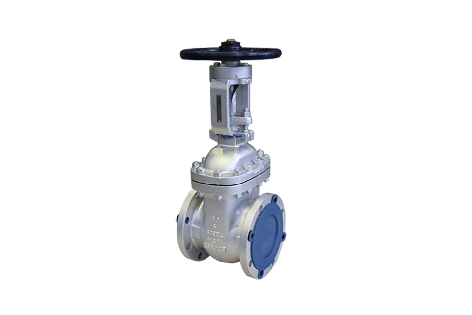
Structural characteristics
① The product design and manufacturing meet the requirements of advanced foreign standards, featuring reliable sealing and excellent performance.
② The structural design is compact and reasonable with an elegant appearance.
③ It adopts a wedge-type elastic gate structure, and rolling bearings are installed for medium and large calibers, ensuring easy opening and closing.
④ A complete range of valve body materials is available. Packings and gaskets are reasonably selected according to actual working conditions or user requirements, making it suitable for various pressure, temperature, and medium conditions.
⑤ It adopts multiple domestic and foreign piping flange standards and flange sealing surface types to meet various engineering needs and user requirements.
Pressure test
| Nominal pressure | Strength test | Water seal test | Airtight seal test | |||
|---|---|---|---|---|---|---|
| MPa | Lbf/in 2 | MPa | Lbf/in 2 | MPa | Lbf/in 2 | |
| 150 | 3.1 | 450 | 2.2 | 315 | 0.5~0.7 | 60~100 |
| 300 | 7.8 | 1125 | 5.6 | 815 | ||
| 600 | 15.3 | 2225 | 11.2 | 1630 | ||
| 900 | 23.1 | 3350 | 16.8 | 2440 | ||
| 1500 | 38.4 | 5575 | 28.1 | 4080 | ||
| 2500 | 64.6 | 9367 | 47.4 | 6873 | ||
Main component materials and performance
| Housing | ASTM 216WCB | ASTM A351 CF8 | |||||||||
| Ram | WCB | CF8 | CF8M | Monel | |||||||
| Valve stem | F6a | F304 | F316 | Monel | F304 | ||||||
| Gate sealing surface | 13Cr | 13Cr | STL | 304 | STL | 316 | STL | Monel | 304 | 304 | STL |
| Seat seals face | 13Cr | STL | STL | 304 | STL | 316 | STL | Monel | 304 | STL | STL |
| Housing | ASTM A351 CF3 | ADTM A351 CF8M | ASTM A351 CF8 | ||||||||
| Ram | |||||||||||
| Valve stem | F304L | F316 | F316L | ||||||||
| Gate sealing surface | 304L | 304L | STL | 316 | 316 | STL | 316L | 316L | STL | ||
| Seat Seals Face | 304L | STL | STL | 316 | STL | STL | 316L | STL | STL | ||
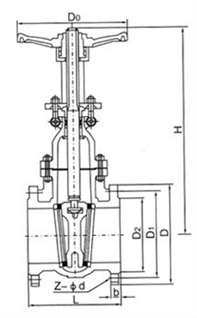
Z41W-150LB American standard gate valve - external parameters and connection dimensions
| Model | Specifications | Size (mm) | ||||||||
|---|---|---|---|---|---|---|---|---|---|---|
| inch | DN | L | D | D1 | D2 | b | z-Φd | H | D0 | |
| Z41W-150Lb | 1/2" | 15 | 108 | 89 | 60.5 | 35 | 12 | 4-Φ15 | 155 | 120 |
| 3/4" | 20 | 117 | 98 | 70 | 43 | 12 | 4-Φ15 | 160 | 120 | |
| 1" | 25 | 127 | 108 | 79.5 | 51 | 12 | 4-Φ15 | 200 | 140 | |
| 11/4" | 32 | 140 | 117 | 89 | 64 | 13 | 4-Φ15 | 245 | 160 | |
| 11/2" | 40 | 165 | 127 | 98.5 | 73 | 15 | 4-Φ15 | 285 | 180 | |
| 2" | 50 | 178 | 152 | 120.5 | 92 | 16 | 4-Φ19 | 315 | 200 | |
| 21/2" | 65 | 190 | 178 | 139.5 | 105 | 18 | 4-Φ19 | 375 | 220 | |
| 3" | 80 | 203 | 190 | 152.5 | 127 | 19 | 4-Φ19 | 400 | 240 | |
| 4" | 100 | 229 | 229 | 190.5 | 157 | 24 | 8-Φ19 | 460 | 280 | |
| 5" | 125 | 254 | 254 | 216 | 186 | 24 | 8-Φ22 | 540 | 300 | |
| 6" | 150 | 267 | 279 | 241.5 | 216 | 26 | 8-Φ22 | 620 | 320 | |
| 8" | 200 | 292 | 343 | 298.5 | 270 | 29 | 8-Φ22 | 800 | 400 | |
| 10" | 250 | 330 | 406 | 362 | 324 | 31 | 12-Φ25 | 850 | 450 | |
| 12" | 300 | 356 | 483 | 432 | 381 | 32 | 12-Φ25 | 1000 | 500 | |
| 14" | 350 | 381 | 533 | 476 | 413 | 35 | 12-Φ29 | 1300 | 600 | |
| 16" | 400 | 406 | 597 | 540 | 470 | 37 | 16-Φ29 | 1400 | 600 | |
| 18" | 450 | 432 | 635 | 578 | 533 | 40 | 16-Φ32 | 1600 | 650 | |
| 20" | 500 | 457 | 698 | 635 | 584 | 43 | 20-Φ32 | 1850 | 650 | |
| 24" | 600 | 508 | 813 | 749.5 | 692 | 48 | 20-Φ35 | 2200 | 700 | |
Z41W-300LB American standard gate valve - external parameters and connection dimensions
| Model | Specifications | Size (mm) | ||||||||
|---|---|---|---|---|---|---|---|---|---|---|
| inch | DN | L | D | D1 | D2 | b | z-Φd | H | D0 | |
| Z41W-300Lb | 1/2" | 15 | 140 | 95 | 66.5 | 35 | 15 | 4-Φ15 | 155 | 120 |
| 3/4" | 20 | 152 | 117 | 82.5 | 43 | 16 | 4-Φ19 | 160 | 120 | |
| 1" | 25 | 165 | 124 | 89 | 51 | 18 | 4-Φ19 | 200 | 140 | |
| 11/4" | 32 | 178 | 133 | 98.5 | 64 | 19 | 4-Φ19 | 250 | 160 | |
| 11/2" | 40 | 190 | 156 | 114.5 | 73 | 21 | 4-Φ22 | 290 | 180 | |
| 2" | 50 | 216 | 165 | 127 | 92 | 22 | 8-Φ19 | 330 | 220 | |
| 21/2" | 65 | 241 | 190 | 149 | 105 | 25 | 8-Φ22 | 385 | 250 | |
| 3" | 80 | 283 | 210 | 168.5 | 127 | 29 | 8-Φ22 | 410 | 280 | |
| 4" | 100 | 305 | 254 | 200 | 157 | 32 | 8-Φ22 | 480 | 300 | |
| 5" | 125 | 381 | 279 | 235 | 186 | 35 | 8-Φ22 | 630 | 350 | |
| 6" | 150 | 403 | 318 | 270 | 216 | 37 | 12-Φ22 | 690 | 350 | |
| 8" | 200 | 419 | 381 | 330 | 270 | 41 | 12-Φ25 | 830 | 450 | |
| 10" | 250 | 457 | 445 | 387.5 | 324 | 48 | 16-Φ29 | 1003 | 500 | |
| 12" | 300 | 502 | 521 | 451 | 381 | 51 | 16-Φ32 | 1137 | 600 | |
| 14" | 350 | 762 | 584 | 514.5 | 413 | 54 | 20-Φ32 | 1489 | 750 | |
| 16" | 400 | 838 | 648 | 571.5 | 470 | 57 | 20-Φ35 | 1581 | 800 | |
| 18" | 450 | 914 | 711 | 628.5 | 533 | 60 | 24-Φ35 | 2017 | 850 | |
| 20" | 500 | 991 | 775 | 686 | 584 | 64 | 24-Φ35 | 2228 | 900 | |
| 24" | 600 | 1143 | 914 | 813 | 692 | 70 | 24-Φ41 | 2650 | 950 | |
Z41W-600LB American standard gate valve - external parameters and connection dimensions
| Z41W-600Lb | 1/2" | 15 | 165 | 95 | 66.5 | 35 | 15 | 4-Φ15 | 155 | 120 |
| 3/4" | 20 | 190 | 118 | 82.5 | 43 | 16 | 4-Φ19 | 160 | 120 | |
| 1" | 25 | 216 | 124 | 89 | 51 | 18 | 4-Φ19 | 200 | 140 | |
| 11/4" | 32 | 229 | 133 | 98.5 | 64 | 21 | 4-Φ19 | 250 | 160 | |
| 11/2" | 40 | 241 | 156 | 114.5 | 73 | 23 | 4-Φ22 | 290 | 180 | |
| 2" | 50 | 292 | 165 | 127 | 92 | 26 | 8-Φ19 | 350 | 250 | |
| 21/2" | 65 | 330 | 190 | 149 | 105 | 29 | 8-Φ22 | 430 | 250 | |
| 3" | 80 | 356 | 210 | 168 | 127 | 32 | 8-Φ22 | 470 | 300 | |
| 4" | 100 | 432 | 273 | 216 | 157 | 38 | 8-Φ25 | 570 | 350 | |
| 5" | 125 | 508 | 330 | 266.5 | 186 | 45 | 8-Φ29 | 700 | 400 | |
| 6" | 150 | 559 | 356 | 292 | 216 | 48 | 12-Φ29 | 750 | 500 | |
| 8" | 200 | 660 | 419 | 349 | 270 | 56 | 12-Φ32 | 830 | 600 | |
| 10" | 250 | 787 | 508 | 432 | 324 | 64 | 16-Φ35 | 1210 | 650 | |
| 12" | 300 | 838 | 559 | 489 | 381 | 67 | 20-Φ35 | 1350 | 700 | |
| 14" | 350 | 889 | 603 | 527 | 413 | 70 | 20-Φ38 | 1600 | 750 | |
| 16" | 400 | 991 | 686 | 603 | 470 | 77 | 20-Φ41 | 1800 | 800 | |
| 18" | 450 | 1092 | 743 | 654 | 533 | 83 | 20-Φ44 | 2110 | 900 | |
| 20" | 500 | 1194 | 813 | 724 | 584 | 89 | 24-Φ44 | 2350 | 950 | |
| 24" | 600 | 1397 | 940 | 838 | 692 | 102 | 24-Φ52 | 2900 |
1000 |
(1) Before installation, check that the product model, tag number, and specifications match the requirements. Inspect the entire valve for missing or loose parts.
(2) Prior to installation, clean the pipeline. Ensure there is sufficient straight pipe section at the valve inlet and install a filter. When connecting the valve body to the pipeline flanges, ensure coaxiality.
(3) Thoroughly clean the pipeline before installing the valve.
(4) The installation site should ensure the safety of personnel and equipment, facilitating operation, disassembly, and maintenance.
(5) The valve should be installed vertically upright on horizontal pipelines. If necessary, it can be installed at an angle, but horizontal installation should be avoided. For occasions with heavy valve weight or vibration, use a support frame.
(6) The medium flow direction must align with the arrow on the valve body. The air supply should be dry and oil-free. The valve should be used in environments with temperatures ranging from -20℃ to 55℃.
(1) Cleaning the Valve: For general media, cleaning with water is sufficient. For media harmful to health, first understand their properties and then select an appropriate cleaning method.
(2) Disassembly: Remove rust from exposed rusted parts first. Before derusting, protect the machined surfaces of precision parts such as the valve seat, valve plug, valve stem, and push rod. Use special tools when disassembling the valve seat.
(3) Valve Seat: Minor rust or wear on the sealing surface can be repaired by machining. If damage is severe, replace the seat. However, both repaired and replaced hard sealing surfaces must be lapped.
(4) Valve Stem: If the surface is damaged, it must be replaced.
(5) Damage to Push Rod, Guide, and Sealing Surfaces: Reverse-acting actuators must be replaced; direct-acting actuators can be reused after proper repair.
(6) Compression Spring: If there are cracks or other defects affecting strength, replace it immediately.
(7) Wear Parts: Packing, gaskets, and O-rings must be replaced entirely during each maintenance. Check the valve plug and diaphragm for cracks, aging, or corrosion that may cause future failures. Decide whether to replace them based on inspection results, but the diaphragm service life should not exceed 2-3 years.
(8) When reassembling the valve, ensure alignment. Tighten bolts diagonally and lubricate sliding parts. After reassembly, debug the valve according to the factory test items and methods. During this period, accurately adjust the packing compression force and the valve plug closing position.
-
If the model has not been selected before ordering, please provide us with the operating parameters:
(1) Nominal diameter DN (mm);
(2) Nominal pressure (MPa or bar);
(3) Fluid properties (including medium temperature, viscosity, or acidity/alkalinity);
(4) Pressure before and after the valve (pressure differential);
(5) Requirements for flow characteristics;
(6) Materials of valve body and valve core;
(7) Connection type;
(8) Driving method (provide air supply pressure, driving voltage);
(9) Supporting accessories (for pneumatic valves, it is recommended that users install an air filter triplet and a 2-position 5-way solenoid valve);
(10) On-site working conditions. -
If the product model of our company has been selected by the design unit, please order directly from our production department according to the model;
-
When the application occasion is very important or the pipeline is relatively complex, please provide the design drawings and detailed parameters as much as possible, and our experts will review and check them for you.


