


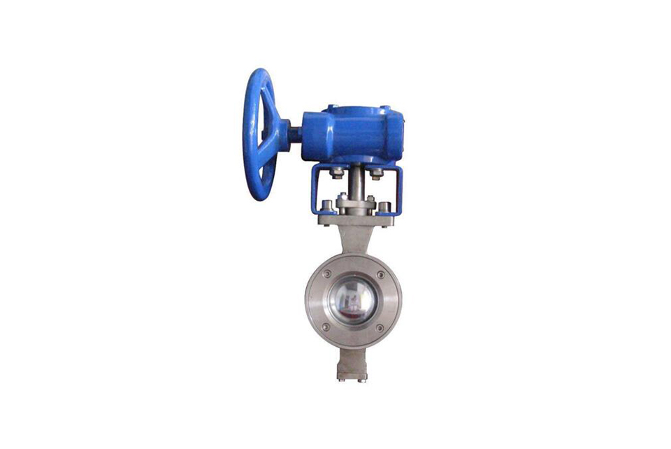
Product Features
Suitable for frequent operation, quick opening and closing, lightweight, low fluid resistance, simple structure, relatively small volume, light weight, easy maintenance, good sealing performance, not limited by installation direction, medium flow direction can be arbitrary, no vibration, low noise.
Suitable for controlling pulp, mortar, and viscous fluids.
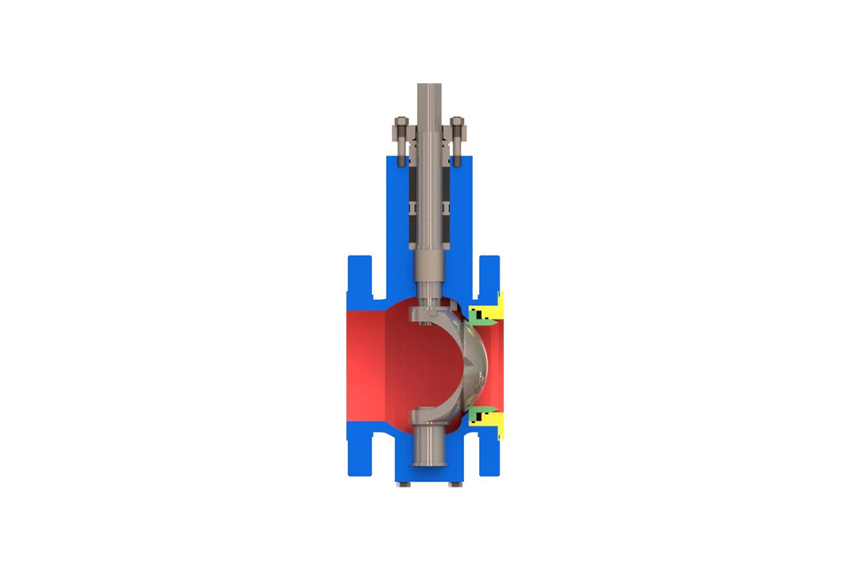
Principle of V-shaped ball valve
Cut off impurities with a wavy edge. During the rotation of the sphere, the V-shaped blade of the sphere is tangent to the valve seat, thereby cutting off fibers and solid substances in the fluid. However, general ball valves do not have this function, which can easily cause fiber impurities to get stuck when closing, causing great inconvenience to maintenance and repair. And the valve core of the V-shaped ball valve will not be stuck by fibers. In addition, due to the use of flange connection, it is easy to disassemble and assemble without the need for special tools, and maintenance is also simple and easy. When the valve is closed. The V-shaped notch and valve seat create a scissor like effect, which not only has self-cleaning function but also prevents the ball core from getting stuck. The valve body, valve cover, and valve seat are each made of metal point-to-point structure, and a valve stem spring with a low friction coefficient is used. Therefore, the operating torque is small and stable.
Main components of V-type ball valve
| Serial number | Name | Quantity (pcs) | Material | ||
|---|---|---|---|---|---|
| 1 | Valve body | 1 | WCB | CF8 | CF8M |
| 2 | Valve core | 1 | CF8 surface hard chrome plated | CF8 surface hard chrome plated | CF8M surface hard chrome plated |
| 3 | Cylindrical pin | 2 | 304 | 304 | 316 |
| 4 | Valve seat | 1 | 304 surfacing hard alloy | 304 surfacing hard alloy | 316 |
| 5 | Spring | 1 | 316 | 316 | 316 |
| 6 | O-ring | 1 | Fluororubber | Fluororubber | Fluororubber |
| 7 | Self-lubricating bearing |
|
304+PTFE | 304+PTFE | 316+PTFE |
| 8 | Lower valve stem | 1 | 20Cr13 | 304 | 316 |
| 9 | O-ring | 1 | Fluororubber | Fluororubber | Fluororubber |
| 10 | Rear gland | 1 | WCB | CF8 | CF8M |
| 11 | Ring gasket | 1 | PTFE | PTFE | PTFE |
| 12 | Adjusting shim | 1 | PTFE | PTFE | PTFE |
| 13 | Flat gasket | 4 | Q235 | 304 | 304 |
| 14 | Bolt | 4 | 25 | 304 | 304 |
| 15 | Stud | 2 | 25 | 304 | 304 |
| 16 | Self-lubricating bearing | 1 | 304+PTFE | 304+PTFE | 316+PTFE |
| 17 | Flat key | 1 | 20Cr13 | 304 | 316 |
| 18 | Lower packing | 1 | PTFE | PTFE | PTFE |
| 19 | Middle packing | 1 set | PTFE | PTFE | PTFE |
| 20 | Upper packing | 1 | PTFE | PTFE | PTFE |
| 21 | Packing gland | 1 | WCB | CF8 | CF8M |
| 22 | Nut | 2 | 35 | 304 | 304 |
| 23 | Upper valve stem | 1 | 20Cr13 | 304 | 316 |
Cv value table of standard V-type ball valve products
| Specification | CV value |
|---|---|
| DN25(1”) | 36 |
| DN32(1 1/4") | 56 |
| DN40(1 1/2") | 94 |
| DN50(2”) | 152 |
| DN65(2 1/2") | 262 |
| DN80(3”) | 358 |
| DN100(4”) | 540 |
| DN125(5”) | 906 |
| DN150(6”) | 1424 |
| DN200(8”) | 2176 |
| DN250(10”) | 3532 |
| DN300(12") | 5732 |
| DN350(14”) | 8245 |
| DN400(16”) | 10651 |
| DN450(18”) | 12878 |
| DN500(20”) | 16343 |
For various types of V-type ball valves, including: wafer-type V-type ball valves, flange-type V-type ball valves, pneumatic double-actuator V-type ball valves, compact pneumatic V-type control valves, and manual worm gear V-type control valves. The Cv value of a V-type ball valve represents the flow capacity of the V-type control valve for liquids; that is, the flow coefficient. It is generally called the Cv value abroad and the Kv value in China. It is an important parameter of valve products.
Calculation formula: Cv = qv * [ρ * △p0 / (ρ0 * △p)]^0.5
Where: Cv: Flow capacity,
USgal/min qv: Measured water flow,
USgal/min ρ: Measured water density, g/cm;
ρ0: Density of water at 60°F, ρ0 = 1g/cm;
△p = p1 - p2. p1 and p2 are the pressure differences between the upstream and downstream of the measured component, lbf/in2.
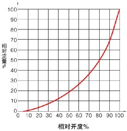
The inherent flow characteristic of the V-type ball valve is an approximate percentage characteristic, as shown in the figure
Maximum allowable leakage of V-type ball valve
| Specification | Maximum allowable leakage of hard seal | Maximum allowable leakage of soft seal valve seat |
|---|---|---|
| DN25(1”) | 1.50ml/min | 0.15ml/min |
| DN32(1 - 1/4") | 1.80ml/min | 0.18ml/min |
| DN40(1 - 1/2") | 2.40ml/min | 0.24ml/min |
| DN50(2”) | 3.00ml/min | 0.30ml/min |
| DN65(2 - 1/2") | 3.90ml/min | 0.39ml/min |
| DN80(3”) | 4.80ml/min | 0.48ml/min |
| DN100(4”) | 6.00ml/min | 0.60ml/min |
| DN125(5”) | 7.50ml/min | 0.75ml/min |
| DN150(6”) | 9.00ml/min | 0.90ml/min |
| DN200(8") | 12.00ml/min | 1.20ml/min |
| DN250(10”) | 15.00ml/min | 1.50ml/min |
| DN300(12”) | 18.00ml/min | 1.80ml/min |
| DN350(14”) | 21.00ml/min | 2.10ml/min |
| DN400(16”) | 24.00ml/min | 2.40ml/min |
| DN450(18”) | 26.00ml/min | 2.60ml/min |
| DN500(20”) | 30.00ml/min | 3.00ml/min |
External dimensions of V-type ball valve
| DN | L | B | H | C | D | D1 |
|---|---|---|---|---|---|---|
| 25 | 168 | 108 | 163 | 120 | 36 | 85 |
| 32 | 168 | 108 | 168 | 120 | 36 | 85 |
| 40 | 204 | 129 | 170 | 130 | 46 | 85 |
| 50 | 262 | 137 | 180 | 130 | 50 | 85 |
| 65 | 262 | 137 | 195 | 130 | 50 | 85 |
| 80 | 268 | 153 | 210 | 145 | 56 | 90 |
| 100 | 268 | 153 | 220 | 145 | 56 | 102 |
| 125 | 300 | 175 | 235 | 160 | 68 | 97 |
| 150 | 390 | 192 | 270 | 160 | 75 | 129 |
| 200 | 460 | 217 | 300 | 175 | 87 | 123 |
| 250 | 525 | 260 | 375 | 195 | 103 | 149 |
| 300 | 600 | 319 | 420 | 220 |
|
148 |
| 350 | 720 | 356 | 500 | 250 |
|
179 |
| 400 | 740 | 378 | 550 | 260 |
|
180 |
| 450 | 740 | 378 | 650 | 260 |
|
230 |
| 500 | 860 | 432 | 720 | 260 |
|
280 |
(1) Before installation, check that the product model, tag number, and specifications match the requirements. Inspect the entire valve for missing or loose parts.
(2) Prior to installation, clean the pipeline. Ensure there is sufficient straight pipe section at the valve inlet and install a filter. When connecting the valve body to the pipeline flanges, ensure coaxiality.
(3) Thoroughly clean the pipeline before installing the valve.
(4) The installation site should ensure the safety of personnel and equipment, facilitating operation, disassembly, and maintenance.
(5) The valve should be installed vertically upright on horizontal pipelines. If necessary, it can be installed at an angle, but horizontal installation should be avoided. For occasions with heavy valve weight or vibration, use a support frame.
(6) The medium flow direction must align with the arrow on the valve body. The air supply should be dry and oil-free. The valve should be used in environments with temperatures ranging from -20℃ to 55℃.
(1) Cleaning the Valve: For general media, cleaning with water is sufficient. For media harmful to health, first understand their properties and then select an appropriate cleaning method.
(2) Disassembly: Remove rust from exposed rusted parts first. Before derusting, protect the machined surfaces of precision parts such as the valve seat, valve plug, valve stem, and push rod. Use special tools when disassembling the valve seat.
(3) Valve Seat: Minor rust or wear on the sealing surface can be repaired by machining. If damage is severe, replace the seat. However, both repaired and replaced hard sealing surfaces must be lapped.
(4) Valve Stem: If the surface is damaged, it must be replaced.
(5) Damage to Push Rod, Guide, and Sealing Surfaces: Reverse-acting actuators must be replaced; direct-acting actuators can be reused after proper repair.
(6) Compression Spring: If there are cracks or other defects affecting strength, replace it immediately.
(7) Wear Parts: Packing, gaskets, and O-rings must be replaced entirely during each maintenance. Check the valve plug and diaphragm for cracks, aging, or corrosion that may cause future failures. Decide whether to replace them based on inspection results, but the diaphragm service life should not exceed 2-3 years.
(8) When reassembling the valve, ensure alignment. Tighten bolts diagonally and lubricate sliding parts. After reassembly, debug the valve according to the factory test items and methods. During this period, accurately adjust the packing compression force and the valve plug closing position.
-
If the model has not been selected before ordering, please provide us with the operating parameters:
(1) Nominal diameter DN (mm);
(2) Nominal pressure (MPa or bar);
(3) Fluid properties (including medium temperature, viscosity, or acidity/alkalinity);
(4) Pressure before and after the valve (pressure differential);
(5) Requirements for flow characteristics;
(6) Materials of valve body and valve core;
(7) Connection type;
(8) Driving method (provide air supply pressure, driving voltage);
(9) Supporting accessories (for pneumatic valves, it is recommended that users install an air filter triplet and a 2-position 5-way solenoid valve);
(10) On-site working conditions. -
If the product model of our company has been selected by the design unit, please order directly from our production department according to the model;
-
When the application occasion is very important or the pipeline is relatively complex, please provide the design drawings and detailed parameters as much as possible, and our experts will review and check them for you.


