


Introduction
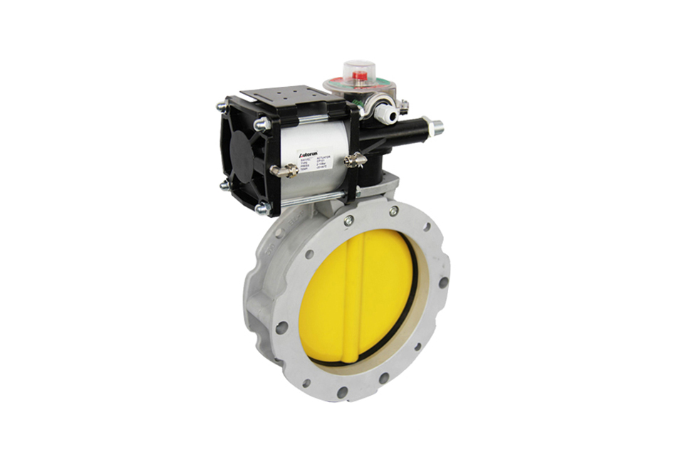
Pneumatic powder butterfly valve is an industrial product specifically designed for powder and granular materials. The soft seal formed by the rubber sealing ring of the pneumatic powder butterfly valve body makes it very suitable for applications involving various powders and granular materials, especially for materials with strong wear resistance. In powder and granular material processing systems that require gravity feeding or pneumatic conveying, pneumatic powder butterfly valves are often installed on hoppers, silos, screw conveyor outlets, and pneumatic conveying pipelines. According to application requirements, a separate drive handle or cylinder drive kit can be selected.
Technical Parameter
Main parameters of pneumatic powder butterfly valve
| Model | BLF | |
|---|---|---|
| Nominal diameter (mm) | DN100 - DN400 | |
| Pressure (Mpa) | 0.6 - 1.6 | |
| Main parts | Valve body | Die - cast aluminum alloy |
| Valve plate | Carbon steel inner lining plate, coated with wear - resistant polymer material | |
| Sealing ring | Nitrile rubber (NBR) | |
| Applicable medium | Cement, mud, powder | |
| Applicable temperature (℃) | -15 - 100 | |
| Pneumatic actuator | Model | CP, GT series, AT series, AW series |
| Pressure (Mpa) | 0.4 - 0.7 | |
Structural diagram and structural dimensions of pneumatic powder butterfly valve BL1F single - flange powder butterfly valve
| Model | φA | φB | φC | φD | E | F | G | φH | φH aperture × quantity | φP outer groove diameter × quantity | φR | S | T | U | V | Z | KG |
|---|---|---|---|---|---|---|---|---|---|---|---|---|---|---|---|---|---|
| BL1F100 | 95 | 180 | 220 | 105 | 250 | 115 | 35 | 22×19 | 14×4 | 20×4 | 220 | 40 | 80 | M12 | 50 | M10 | 4 |
| BL1F150 | 150 | 200 | 228 | 163 | 290 | 115 | 35 | 22×19 | 14×4 | 20×4 | 228 | 40 | 80 | M12 | 50 | M10 | 5 |
| BL1F200 | 200 | 250 | 278 | 213 | 340 | 115 | 35 | 22×19 | 14×4 | 20×4 | 278 | 40 | 80 | M12 | 50 | M10 | 6.5 |
| BL1F250 | 250 | 300 | 328 | 263 | 390 | 115 | 35 | 22×19 | 14×8 | 20×8 | 328 | 40 | 80 | M12 | 50 | M10 | 7.5 |
| BL1F300 | 300 | 350 | 378 | 313 | 440 | 115 | 35 | 22×19 | 14×8 | 20×16 | 378 | 40 | 80 | M12 | 50 | M10 | 9 |
| BL1F350 | 350 | 400 | 440 | 363 | 530 | 123 | 50 | 28×25 | 14×8 | 20×8 | 440 | 40 | 80 | M12 | 50 | M10 | 16 |
| BL1F400 | 400 | 470 | 530 | 413 | 580 | 123 | 50 | 28×25 | 14×8 | 20×16 | 530 | 40 | 80 | M12 | 50 | M10 | 20.5 |
Structural diagram and connection dimensions of pneumatic powder butterfly valve BL2F double - flange powder butterfly valve
| Model | φA | φB | φC | φD | E | F | G | φH | φH aperture × quantity | φP outer groove diameter × quantity | φR | S | T | U | V | Z | KG |
|---|---|---|---|---|---|---|---|---|---|---|---|---|---|---|---|---|---|
| BL2F100 | 95 | 180 | 220 | - | 250 | 77 | 35 | 22×19 | 14×4 | 20×4 | 220 | - | 80 | M12 | 50 | M10 | 4 |
| BL1F150 | 150 | 200 | 228 | - | 290 | 77 | 35 | 22×19 | 14×4 | 20×4 | 228 | - | 80 | M12 | 50 | M10 | 5 |
| BL2F200 | 200 | 250 | 278 | - | 340 | 77 | 35 | 22×19 | 14×4 | 20×4 | 278 | - | 80 | M12 | 50 | M10 | 6.5 |
| BL2F250 | 250 | 300 | 328 | - | 390 | 115 | 35 | 22×19 | 14×8 | 20×8 | 328 | - | 80 | M12 | 50 | M10 | 7.5 |
| BL1F300 | 300 | 350 | 378 | - | 440 | 115 | 77 | 22×19 | 14×8 | 20×16 | 378 | - | 80 | M12 | 50 | M10 | 9 |
| BL2F350 | 350 | 400 | 440 | - | 530 | 85 | 50 | 28×25 | 14×8 | 20×8 | 440 | - | 80 | M12 | - | - | 16 |
| BL2F400 | 400 | 470 | 530 | - | 580 | 85 | 50 | 28×25 | 14×8 | 20×16 | 530 | - | 80 | M12 | - | - | 20.5 |
Valve Installation & Maintenance
Valve Installation:
(1) Before installation, check that the product model, tag number, and specifications match the requirements. Inspect the entire valve for missing or loose parts.
(2) Prior to installation, clean the pipeline. Ensure there is sufficient straight pipe section at the valve inlet and install a filter. When connecting the valve body to the pipeline flanges, ensure coaxiality.
(3) Thoroughly clean the pipeline before installing the valve.
(4) The installation site should ensure the safety of personnel and equipment, facilitating operation, disassembly, and maintenance.
(5) The valve should be installed vertically upright on horizontal pipelines. If necessary, it can be installed at an angle, but horizontal installation should be avoided. For occasions with heavy valve weight or vibration, use a support frame.
(6) The medium flow direction must align with the arrow on the valve body. The air supply should be dry and oil-free. The valve should be used in environments with temperatures ranging from -20℃ to 55℃.
Valve Maintenance:
(1) Cleaning the Valve: For general media, cleaning with water is sufficient. For media harmful to health, first understand their properties and then select an appropriate cleaning method.
(2) Disassembly: Remove rust from exposed rusted parts first. Before derusting, protect the machined surfaces of precision parts such as the valve seat, valve plug, valve stem, and push rod. Use special tools when disassembling the valve seat.
(3) Valve Seat: Minor rust or wear on the sealing surface can be repaired by machining. If damage is severe, replace the seat. However, both repaired and replaced hard sealing surfaces must be lapped.
(4) Valve Stem: If the surface is damaged, it must be replaced.
(5) Damage to Push Rod, Guide, and Sealing Surfaces: Reverse-acting actuators must be replaced; direct-acting actuators can be reused after proper repair.
(6) Compression Spring: If there are cracks or other defects affecting strength, replace it immediately.
(7) Wear Parts: Packing, gaskets, and O-rings must be replaced entirely during each maintenance. Check the valve plug and diaphragm for cracks, aging, or corrosion that may cause future failures. Decide whether to replace them based on inspection results, but the diaphragm service life should not exceed 2-3 years.
(8) When reassembling the valve, ensure alignment. Tighten bolts diagonally and lubricate sliding parts. After reassembly, debug the valve according to the factory test items and methods. During this period, accurately adjust the packing compression force and the valve plug closing position.
Ordering Instructions
When placing an order, please fill in the Specification Sheet or specify the following information:
-
If the model has not been selected before ordering, please provide us with the operating parameters:
(1) Nominal diameter DN (mm);
(2) Nominal pressure (MPa or bar);
(3) Fluid properties (including medium temperature, viscosity, or acidity/alkalinity);
(4) Pressure before and after the valve (pressure differential);
(5) Requirements for flow characteristics;
(6) Materials of valve body and valve core;
(7) Connection type;
(8) Driving method (provide air supply pressure, driving voltage);
(9) Supporting accessories (for pneumatic valves, it is recommended that users install an air filter triplet and a 2-position 5-way solenoid valve);
(10) On-site working conditions. -
If the product model of our company has been selected by the design unit, please order directly from our production department according to the model;
-
When the application occasion is very important or the pipeline is relatively complex, please provide the design drawings and detailed parameters as much as possible, and our experts will review and check them for you.


