


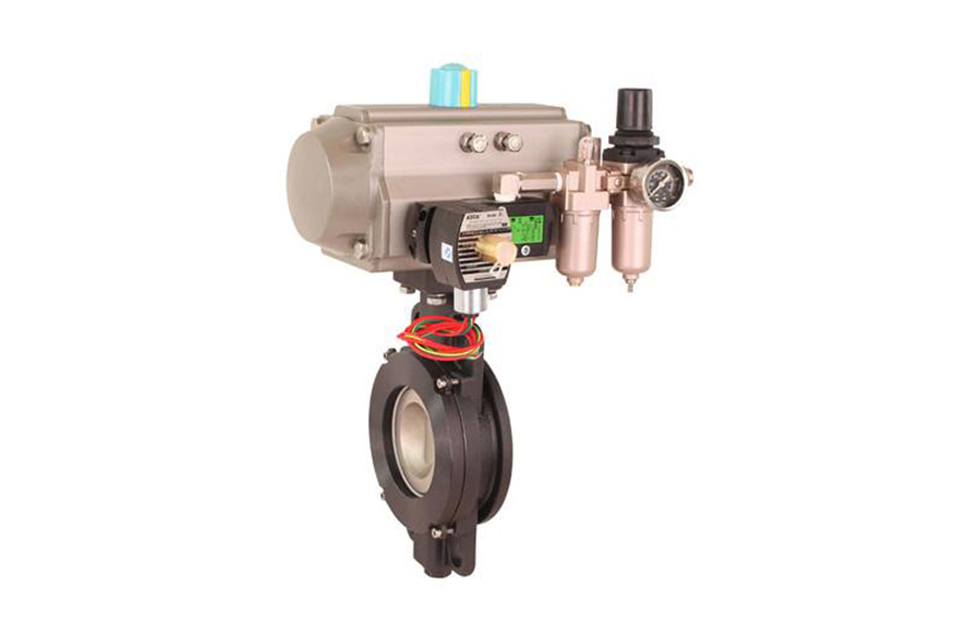
Product Features
(1) The pneumatic hard seal butterfly valve adopts a three eccentric sealing structure, with almost no wear on the valve seat and butterfly plate, and has a sealing function that becomes tighter as viewed.
(2) The sealing ring is made of stainless steel, which has the dual advantages of metal hard sealing and elastic sealing. It has excellent sealing performance in both low and high temperatures, corrosion resistance, and long service life.
(3) The sealing surface of the butterfly plate is made of welded cobalt based hard alloy, which is wear-resistant and has a long service life
(4) The large-sized butterfly plate adopts a frame structure with high strength, large overcurrent area, and low flow resistance.
(5) Pneumatic hard seal butterfly valve has bidirectional sealing function, which is not limited by the flow direction of the medium or the spatial position during installation, and can be installed in any direction.
(6) The pneumatic device can be installed in multiple stations (rotating 90 ° or 180 °), making it easy for users to use.
Product Selection
(1) Valve body parameters: nominal diameter, working pressure, process medium, usage scenario, valve body material, and other series of parameters.
(2) Actuator parameters: actuator form, control mode, control signal (4-20mA, 1-5V), action mode (air open, air closed)
Please provide the above technical parameters as detailed as possible to facilitate our company's production and technical personnel to accurately select for you. If you have any questions You can call us and we will do our best to provide you with high-quality service!
Pneumatic Hard-Sealed Butterfly Valve Technical Parameters
| Nominal Diameter DN (mm) | DN50 - 1000mm |
|---|---|
| Nominal Pressure (MPa) | PN1.0, 1.6, 2.5MPa |
| Valve Body Form | Straight-through Cast Valve Body |
| Connection Form | Flange Type, Wafer Type |
| Valve Core Form | Butterfly Plate Type |
| Sealing Packing | Flexible Graphite, Polytetrafluoroethylene |
| Flow Characteristic | Approximately Equal Percentage, Linear |
| Action Range | 0 - 90° |
| Leakage Quantity Q | Complies with ANSI B16.104 Class IV Standard |
| Applicable Temperature | Hard Seal ≤ 450°C |
| Basic Error | With Positioner: Less than ±2% of Full Stroke |
| Hysteresis | With Positioner: Less than 2% of Full Stroke |
| Adjustable Range | 50:1 |
| Configured Actuator | GT, AT, AR, AW Series Single and Double Acting Pneumatic Actuators |
| Control Method | On-Off Two-Position Control, 4 - 20mA Analog Control |
Pneumatic Hard-Sealed Butterfly Valve Actuator Parameters
| Actuator Model | GT, AT, AR, AW Series Single and Double Acting Pneumatic Actuators |
|---|---|
| Supply Pressure | 0.4 - 0.7MPa |
| Air Source Interface | G1/4", G1/8", G3/8", G1/2" |
| Ambient Temperature | -30 - +70°C |
| Action Form |
Single Acting Actuator: Air-Closed (B) - Valve Position Open (FO) when Air is Lost; Air-Open (K) - Valve Position Closed (FC) when Air is Lost Double Acting Actuator: Air-Closed (B) - Valve Position Maintained (FL) when Air is Lost; Air-Open (K) - Valve Position Maintained (FL) when Air is Lost |
| Compatible Accessories | Positioner, Solenoid Valve, Air Filter Regulator, Position Maintaining Valve, Travel Switch, Valve Position Transmitter, Handwheel Mechanism, etc. |
The new series of pneumatic actuators are adopted, including double acting type and single acting type (spring return), with gear and rack transmission, which is safe and reliable; Large-diameter valves adopt the series AW type pneumatic actuator with fork transmission, which has a reasonable structure, large output torque, and includes double acting type and single acting type.
1. Gear-type double piston, with large output torque and small volume.
2. The cylinder is made of aluminum alloy material, with light weight and beautiful appearance.
3. Manual operation mechanisms can be installed on the top and bottom.
4. The rack connection can adjust the opening angle and rated flow.
5. The actuator can be optionally equipped with electrical signal feedback indication and various accessories to achieve automatic operation.
6. The ISO5211 standard connection provides convenience for the installation and replacement of products.
7. The adjusting screws at both ends can make the standard product have an adjustable range of ±4° at 0° and 90°. Ensure the synchronization accuracy with the valve.
Pneumatic Hard-Sealed Butterfly Valve Part Materials
| Part Name | Material |
|---|---|
| Valve Body | Cast Iron, Stainless Steel, Chromium-Molybdenum Steel, Alloy Steel |
| Butterfly Plate | Cast Steel, Alloy Steel, Stainless Steel, Chromium-Molybdenum Steel |
| Sealing Ring | Multi-layer Combination of Stainless Steel and High-Temperature Resistant Asbestos Board |
| Valve Stem | 2Cr13, 1Cr13 Stainless Steel, Chromium-Molybdenum Steel |
| Packing | O-Ring, Flexible Graphite |
Pneumatic Hard-Sealed Butterfly Valve Performance Specifications
| Nominal Diameter DN (mm) | DN50 - 1200 | ||||
|---|---|---|---|---|---|
| Nominal Pressure | PN (MPa) | 0.6 | 1.0 | 1.6 | 2.5 |
| Test Pressure | Strength Test | 0.9 | 1.5 | 2.4 | 3.75 |
| Sealing Test | 0.66 | 1.1 | 1.76 | 2.75 | |
| Low-Pressure Air Tightness Test | 0.5 - 0.7 | ||||
| Applicable Medium | Air, Water, Sewage, Steam, Gas, Oil, etc. | ||||
| Applicable Temperature | Carbon Steel: -29°C - 600°C; Stainless Steel: -40°C - 600°C | ||||
Pneumatic Hard-Sealed Butterfly Valve Design Standards
| Design Standard | GB/T12238 - 1989 |
| Flange Connection Dimensions | GB/T9113.1 - 2000; GB/T9115.1 - 2000; JB78 |
| Structural Length | GB/T12221 - 1989 |
| Pressure Test | GB/T13927 - 2000; JB/T9092 - 1999 |
Pneumatic Hard-Sealed Butterfly Valve Eccentric Principle
(1) Deviate from the pipe center
(2) Deviate from the sealing surface center
(3) Inclined cone
When the valve is opened, the butterfly plate contacts the valve seat instantaneously when closing. By using the two eccentricities of the butterfly plate (eccentricity 1 and eccentricity 2), it quickly disengages from the valve seat, reducing the wear of the sealing pair, with small friction torque and flexible opening. The eccentric cone surface 3 enables the butterfly plate to pass through the inner hole of the valve seat when the valve is opened or closed, achieving contact sealing. In addition, the rotation radius of the conical butterfly plate is larger than that of the contact position of the sealing pair. Therefore, when the valve is closed, the butterfly plate will be tightened more and more, achieving self-locking and preventing the butterfly plate from over-positioning.
| Pneumatic Three-Eccentric Hard-Sealed Butterfly Valve (Eccentric Principle) | Pneumatic Three-Eccentric Hard-Sealed Butterfly Valve (Sealing Principle) |
|---|
Pneumatic Hard-Sealed Butterfly Valve Connection Dimension Diagram
| D643H Pneumatic Hard-Sealed Butterfly Valve (Flange Type) | D673H Pneumatic Hard-Sealed Butterfly Valve (Wafer Type) |
|---|
Pneumatic Hard-Sealed Butterfly Valve Connection Dimensions
| Nominal Diameter (DN) | Main Dimensions | Flange Dimensions | ||||||||||||
|---|---|---|---|---|---|---|---|---|---|---|---|---|---|---|
| L (Structural Length) | H | H1 | A | 1.0MPa | 1.6MPa | 2.5MPa | ||||||||
| Flange | Wafer | D | D1 | n-Фd | D | D1 | n-Фd | D | D1 | n-Фd | ||||
| 50 | 108 | 43 | 112 | 625 | 245 | 165 | 125 | 4 - 18 | 165 | 125 | 4 - 18 | 165 | 125 | 4 - 18 |
| 65 | 112 | 46 | 115 | 625 | 245 | 185 | 145 | 4 - 18 | 185 | 145 | 4 - 18 | 185 | 145 | 8 - 18 |
| 80 | 114 | 46 | 120 | 645 | 245 | 200 | 160 | 4 - 18 | 200 | 160 | 8 - 18 | 200 | 160 | 8 - 18 |
| 100 | 127 | 52 | 138 | 675 | 355 | 220 | 180 | 8 - 18 | 220 | 180 | 8 - 18 | 235 | 190 | 8 - 22 |
| 125 | 140 | 56 | 164 | 715 | 355 | 250 | 210 | 8 - 18 | 250 | 210 | 8 - 18 | 270 | 220 | 8 - 26 |
| 150 | 140 | 56 | 175 | 800 | 355 | 285 | 240 | 8 - 22 | 285 | 240 | 8 - 22 | 300 | 250 | 8 - 26 |
| 200 | 152 | 60 | 200 | 850 | 250 | 340 | 295 | 8 - 22 | 340 | 295 | 12 - 22 | 360 | 310 | 12 - 26 |
| 250 | 165 | 68 | 243 | 925 | 250 | 395 | 350 | 12 - 22 | 405 | 355 | 12 - 26 | 425 | 370 | 12 - 30 |
| 300 | 178 | 78 | 250 | 1035 | 450 | 445 | 400 | 12 - 22 | 460 | 410 | 12 - 26 | 485 | 430 | 16 - 30 |
| 350 | 190 | 78 | 280 | 1070 | 450 | 505 | 460 | 16 - 22 | 520 | 470 | 12 - 26 | 555 | 490 | 16 - 33 |
| 400 | 216 | 102 | 305 | 1190 | 450 | 565 | 515 | 16 - 26 | 580 | 525 | 16 - 26 | 620 | 550 | 16 - 36 |
| 450 | 222 | 114 | 350 | 1250 | 650 | 615 | 565 | 20 - 26 | 640 | 585 | 16 - 30 | 670 | 600 | 20 - 36 |
| 500 | 229 | 127 | 380 | 1290 | 650 | 670 | 620 | 20 - 26 | 715 | 650 | 20 - 30 | 730 | 660 | 20 - 36 |
| 600 | 267 | 154 | 445 | 1455 | 850 | 780 | 725 | 20 - 30 | 840 | 770 | 20 - 33 | 845 | 770 | 20 - 39 |
| 700 | 292 | 165 | 480 | 1585 | 850 | 895 | 840 | 24 - 30 | 910 | 840 | 24 - 36 | 960 | 875 | 24 - 42 |
| 800 | 318 | 190 | 530 | 1700 | 1250 | 1015 | 950 | 24 - 33 | 1025 | 950 | 24 - 39 | 1085 | 990 | 24 - 48 |
| 900 | 330 | 203 | 580 | 1965 | 1250 | 1115 | 1050 | 28 - 33 | 1125 | 1050 | 28 - 39 | 1185 | 1090 | 28 - 48 |
| 1000 | 410 | 216 | 650 | 2015 | 1250 | 1230 | 1160 | 28 - 36 | 1255 | 1170 | 28 - 42 | 1320 | 1210 | 28 - 56 |
| 1200 | 470 | 254 | 760 | 2250 | 1250 | 1455 | 1380 | 32 - 39 | 1485 | 1390 | 32 - 48 | 1530 | 1420 |
32 - 56 |
(1) Before installation, check that the product model, tag number, and specifications match the requirements. Inspect the entire valve for missing or loose parts.
(2) Prior to installation, clean the pipeline. Ensure there is sufficient straight pipe section at the valve inlet and install a filter. When connecting the valve body to the pipeline flanges, ensure coaxiality.
(3) Thoroughly clean the pipeline before installing the valve.
(4) The installation site should ensure the safety of personnel and equipment, facilitating operation, disassembly, and maintenance.
(5) The valve should be installed vertically upright on horizontal pipelines. If necessary, it can be installed at an angle, but horizontal installation should be avoided. For occasions with heavy valve weight or vibration, use a support frame.
(6) The medium flow direction must align with the arrow on the valve body. The air supply should be dry and oil-free. The valve should be used in environments with temperatures ranging from -20℃ to 55℃.
(1) Cleaning the Valve: For general media, cleaning with water is sufficient. For media harmful to health, first understand their properties and then select an appropriate cleaning method.
(2) Disassembly: Remove rust from exposed rusted parts first. Before derusting, protect the machined surfaces of precision parts such as the valve seat, valve plug, valve stem, and push rod. Use special tools when disassembling the valve seat.
(3) Valve Seat: Minor rust or wear on the sealing surface can be repaired by machining. If damage is severe, replace the seat. However, both repaired and replaced hard sealing surfaces must be lapped.
(4) Valve Stem: If the surface is damaged, it must be replaced.
(5) Damage to Push Rod, Guide, and Sealing Surfaces: Reverse-acting actuators must be replaced; direct-acting actuators can be reused after proper repair.
(6) Compression Spring: If there are cracks or other defects affecting strength, replace it immediately.
(7) Wear Parts: Packing, gaskets, and O-rings must be replaced entirely during each maintenance. Check the valve plug and diaphragm for cracks, aging, or corrosion that may cause future failures. Decide whether to replace them based on inspection results, but the diaphragm service life should not exceed 2-3 years.
(8) When reassembling the valve, ensure alignment. Tighten bolts diagonally and lubricate sliding parts. After reassembly, debug the valve according to the factory test items and methods. During this period, accurately adjust the packing compression force and the valve plug closing position.
-
If the model has not been selected before ordering, please provide us with the operating parameters:
(1) Nominal diameter DN (mm);
(2) Nominal pressure (MPa or bar);
(3) Fluid properties (including medium temperature, viscosity, or acidity/alkalinity);
(4) Pressure before and after the valve (pressure differential);
(5) Requirements for flow characteristics;
(6) Materials of valve body and valve core;
(7) Connection type;
(8) Driving method (provide air supply pressure, driving voltage);
(9) Supporting accessories (for pneumatic valves, it is recommended that users install an air filter triplet and a 2-position 5-way solenoid valve);
(10) On-site working conditions. -
If the product model of our company has been selected by the design unit, please order directly from our production department according to the model;
-
When the application occasion is very important or the pipeline is relatively complex, please provide the design drawings and detailed parameters as much as possible, and our experts will review and check them for you.


