


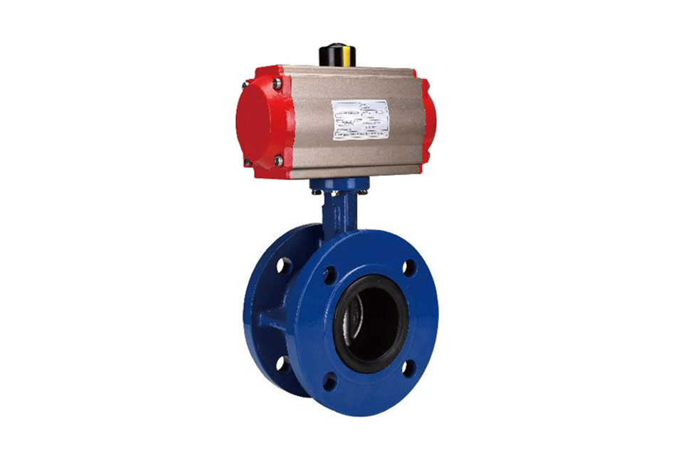
Product Features
(1) The combination of nylon coating and epoxy resin coating meets environmental protection requirements.
(2) The valve plate has a unique design, with a high flow coefficient and low flow resistance. Achieve zero leakage at rated pressure.
(3) Adopting a half axis no pin connection, the structure is simple and compact, and maintenance and disassembly are extremely convenient and fast (can be disassembled on site). The butterfly plate has an automatic centering function, achieving an interference fit between the butterfly plate and the valve seat.
(4) The valve stem sealing ring plays a bidirectional sealing role, avoiding the outflow of medium and preventing foreign substances from entering, achieving zero leakage of the entire valve.
(5) Pneumatic rubber lined butterfly valves have good cutting and regulating performance, can achieve bubble level sealing, small opening and closing torque, and long service life.
Product Selection
(1) Valve body parameters: nominal diameter, working pressure, process medium, usage scenario, valve body material, and other series of parameters.
(2) Actuator parameters: actuator form, control mode, control signal (4-20mA, 1-5V), action mode (air open, air closed)
Please provide the above technical parameters as detailed as possible to facilitate our company's production and technical personnel to accurately select for you. If you have any questions You can call us and we will do our best to provide you with high-quality service!
Pneumatic Rubber-Lined Butterfly Valve - Part Materials
| Part Name | Material |
|---|---|
| Valve Body | Ductile Cast Steel + NBR, Cast Steel + NBR, Stainless Steel + NBR |
| Disc | Gray Cast Iron, Ductile Cast Steel, Cast Steel, Stainless Steel and Special Materials |
| Valve Stem | 2Cr13, Stainless Steel |
| Packing | O-Ring, Flexible Graphite |
Pneumatic Rubber-Lined Butterfly Valve - Performance Specifications
| Nominal Diameter DN (mm) | DN50 - 1200 | |||
|---|---|---|---|---|
| Nominal Pressure | PN (MPa) | 0.6 | 1.0 | 1.6 |
| Test Pressure | Strength Test | 0.9 | 1.5 | 2.4 |
| Sealing Test | 0.66 | 1.1 | 1.76 | |
| Low-Pressure Air Tightness Test | 0.5 - 0.7 | |||
| Applicable Media | Air, Water, Sewage, Steam, Gas, Oil, etc. | |||
Pneumatic Rubber-Lined Butterfly Valve - Connection Dimension Diagram
| D671J Pneumatic Flanged Rubber-Lined Butterfly Valve | D671J Pneumatic Wafer-Type Rubber-Lined Butterfly Valve |
|---|
Pneumatic Rubber-Lined Butterfly Valve - Connection Dimensions
| Nominal Diameter (DN) | Main Dimensions | Flange Dimensions | |||||||||
|---|---|---|---|---|---|---|---|---|---|---|---|
| L | L1 | H | H1 | A | 1.0 MPa | 1.6 MPa | |||||
| D | D1 | n-Фd | D | D1 | n-Фd | ||||||
| 50 | 108 | 43 | 63 | 315 | 180 | 165 | 125 | 4 - 18 | 165 | 125 | 4 - 18 |
| 65 | 112 | 46 | 70 | 330 | 180 | 185 | 145 | 4 - 18 | 185 | 145 | 4 - 18 |
| 80 | 114 | 46 | 83 | 390 | 245 | 200 | 160 | 4 - 18 | 200 | 160 | 8 - 18 |
| 100 | 127 | 52 | 105 | 431 | 240 | 220 | 180 | 8 - 18 | 220 | 180 | 8 - 18 |
| 125 | 140 | 56 | 115 | 455 | 240 | 250 | 210 | 8 - 18 | 250 | 210 | 8 - 18 |
| 150 | 140 | 56 | 137 | 626 | 350 | 285 | 240 | 8 - 22 | 285 | 240 | 8 - 22 |
| 200 | 152 | 60 | 164 | 720 | 350 | 340 | 295 | 8 - 22 | 340 | 295 | 12 - 22 |
| 250 | 165 | 68 | 206 | 800 | 550 | 395 | 350 | 12 - 22 | 405 | 355 | 12 - 26 |
| 300 | 178 | 78 | 230 | 860 | 600 | 445 | 400 | 12 - 22 | 460 | 410 | 12 - 26 |
| 350 | 190 | 78 | 248 | 883 | 600 | 505 | 460 | 16 - 22 | 520 | 470 | 12 - 26 |
| 400 | 216 | 102 | 289 | 972 | 600 | 565 | 515 | 16 - 26 | 580 | 525 | 16 - 26 |
| 450 | 222 | 114 | 320 | 1043 | 750 | 615 | 565 | 20 - 26 | 640 | 585 | 16 - 30 |
| 500 | 229 | 127 | 342 | 1098 | 750 | 670 | 620 | 20 - 26 | 715 | 650 | 20 - 30 |
| 600 | 267 | 154 | 413 | 1236 | 750 | 780 | 725 | 20 - 30 | 840 | 770 | 20 - 33 |
| 700 | 430 | 165 | 478 | 1431 | 750 | 895 | 840 | 24 - 30 | 910 | 840 | 24 - 36 |
| 800 | 470 | 190 | 525 | 1488 | 750 | 1015 | 950 | 24 - 33 | 1025 | 950 | 24 - 39 |
| 900 | 510 | 203 | 585 | 1615 | 1250 | 1115 | 1050 | 28 - 33 | 1125 | 1050 | 28 - 39 |
| 1000 | 550 | 216 | 640 | 1765 | 1500 | 1230 | 1160 | 28 - 36 | 1255 | 1170 | 28 - 42 |
| 1200 | 630 | 254 | 755 | 1976 | 1500 | 1455 | 1380 | 32 - 39 | 1485 | 1390 | 32 - 48 |
(1) Before installation, check that the product model, tag number, and specifications match the requirements. Inspect the entire valve for missing or loose parts.
(2) Prior to installation, clean the pipeline. Ensure there is sufficient straight pipe section at the valve inlet and install a filter. When connecting the valve body to the pipeline flanges, ensure coaxiality.
(3) Thoroughly clean the pipeline before installing the valve.
(4) The installation site should ensure the safety of personnel and equipment, facilitating operation, disassembly, and maintenance.
(5) The valve should be installed vertically upright on horizontal pipelines. If necessary, it can be installed at an angle, but horizontal installation should be avoided. For occasions with heavy valve weight or vibration, use a support frame.
(6) The medium flow direction must align with the arrow on the valve body. The air supply should be dry and oil-free. The valve should be used in environments with temperatures ranging from -20℃ to 55℃.
(1) Cleaning the Valve: For general media, cleaning with water is sufficient. For media harmful to health, first understand their properties and then select an appropriate cleaning method.
(2) Disassembly: Remove rust from exposed rusted parts first. Before derusting, protect the machined surfaces of precision parts such as the valve seat, valve plug, valve stem, and push rod. Use special tools when disassembling the valve seat.
(3) Valve Seat: Minor rust or wear on the sealing surface can be repaired by machining. If damage is severe, replace the seat. However, both repaired and replaced hard sealing surfaces must be lapped.
(4) Valve Stem: If the surface is damaged, it must be replaced.
(5) Damage to Push Rod, Guide, and Sealing Surfaces: Reverse-acting actuators must be replaced; direct-acting actuators can be reused after proper repair.
(6) Compression Spring: If there are cracks or other defects affecting strength, replace it immediately.
(7) Wear Parts: Packing, gaskets, and O-rings must be replaced entirely during each maintenance. Check the valve plug and diaphragm for cracks, aging, or corrosion that may cause future failures. Decide whether to replace them based on inspection results, but the diaphragm service life should not exceed 2-3 years.
(8) When reassembling the valve, ensure alignment. Tighten bolts diagonally and lubricate sliding parts. After reassembly, debug the valve according to the factory test items and methods. During this period, accurately adjust the packing compression force and the valve plug closing position.
-
If the model has not been selected before ordering, please provide us with the operating parameters:
(1) Nominal diameter DN (mm);
(2) Nominal pressure (MPa or bar);
(3) Fluid properties (including medium temperature, viscosity, or acidity/alkalinity);
(4) Pressure before and after the valve (pressure differential);
(5) Requirements for flow characteristics;
(6) Materials of valve body and valve core;
(7) Connection type;
(8) Driving method (provide air supply pressure, driving voltage);
(9) Supporting accessories (for pneumatic valves, it is recommended that users install an air filter triplet and a 2-position 5-way solenoid valve);
(10) On-site working conditions. -
If the product model of our company has been selected by the design unit, please order directly from our production department according to the model;
-
When the application occasion is very important or the pipeline is relatively complex, please provide the design drawings and detailed parameters as much as possible, and our experts will review and check them for you.


