


Model Specifications
| Category | Pressure Control Regulating Valves | Differential Pressure Control Regulating Valves | ||||||
|---|---|---|---|---|---|---|---|---|
| Post-Valve Pressure Regulating Valves | Pre-Valve Pressure Regulating Valves | Valves Close When Differential Pressure Rises | Valves Open When Differential Pressure Rises | |||||
| Hard Seal | Soft Seal | Hard Seal | Soft Seal | Hard Seal | Soft Seal | Hard Seal | Soft Seal | |
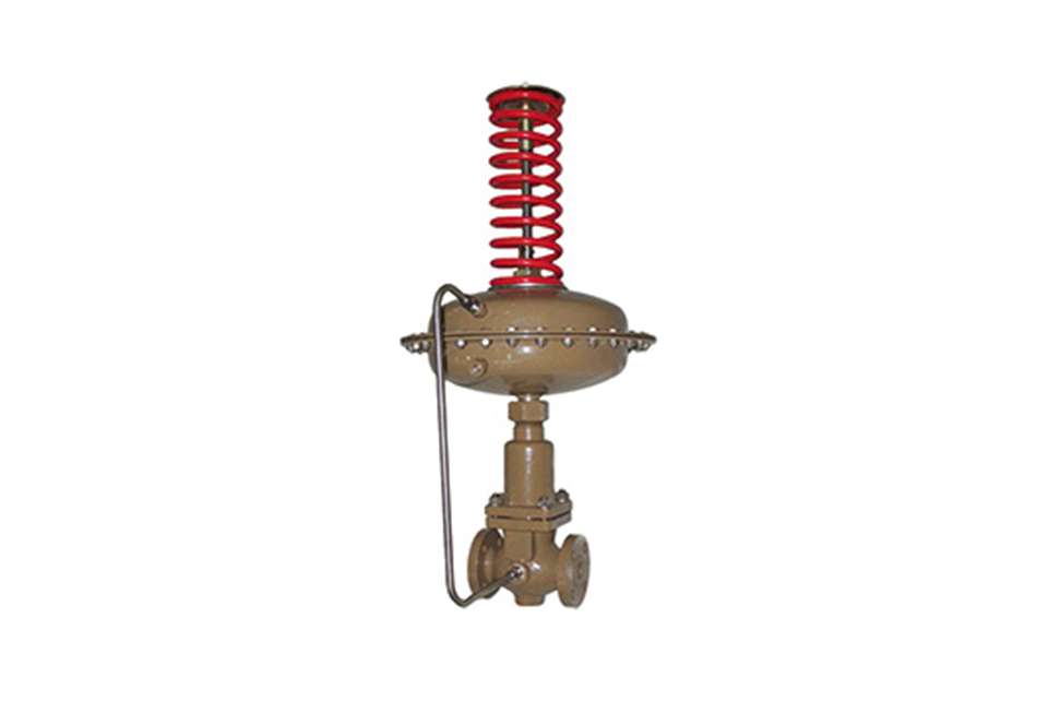
| Model | V230D01 | V230D01 | V230D02 | V230D02 | V230D03 | V230D03 | V230D04 | V230D04 |
| Specification | DN15 - 250 | |||||||
Main Technical Parameters
| Nominal Diameter (mm) | 15 | 20 | 25 | 32 | 40 | 50 | 65 | 80 | 100 | 125 | 150 | 200 | 250 | |
|---|---|---|---|---|---|---|---|---|---|---|---|---|---|---|
| Rated Flow Coefficient Kvs | 3.2 | 5 | 8 | 12.5 | 20 | 32 | 50 | 80 | 125 | 160 | 320 | 450 | 630 | |
| Nominal Pressure (Mpa) | 1.6; 4.0 | |||||||||||||
| Z Value | 0.6 | 0.6 | 0.6 | 0.55 | 0.55 | 0.5 | 0.5 | 0.45 | 0.4 | 0.35 | 0.3 | 0.2 | 0.2 | |
|
Maximum Operating Temperature (℃) |
V230 V231 |
Liquid ≤ 140; Gas ≤ 80 | ||||||||||||
|
Hard Seal V230 |
With Isolation Tank ≤ 200 |
With Isolation Tank and Extension Piece ≤ 300 |
||||||||||||
| With Isolation Tank and Heat Sink ≤ 200 | ||||||||||||||
| Pressure Balancing Element | Bellows | Rolling Diaphragm | ||||||||||||
| Flange Standard | DIA (Flange standards can also be provided according to user requirements) | |||||||||||||
| Valve Body Material | PN16: Cast Iron (Operating Temperature ≤ 200℃); PN40: Cast Steel, Cast Stainless Steel (Operating Temperature ≤ 350℃) | |||||||||||||
| Valve Core Material | Stainless Steel: Soft seal is stainless steel inlaid with rubber ring | |||||||||||||
| Maximum Operating Pressure (MPa) | Nominal Pressure (Note the relationship between △Pmax, operating pressure, and operating temperature) | |||||||||||||
Note:
1. When the liquid temperature is > 140℃ or the gas temperature is > 80℃, the valve should be installed upside down.
2. Z value: Noise measurement system, which is used to measure the noise level. For specific calculations, please refer to the Self - Acting Regulating Valve Selection Guide.
Main Technical Parameters of the Actuator
| Model |
V230 D01(D03) V231D01(D03) |
V230 D02(D04) V231D02(D04) |
||||||
|---|---|---|---|---|---|---|---|---|
| Effective Area (cm²) | 23※ | 80※ | 250 | 630 | 23※ | 80※ | 250 | 630 |
| Pressure Setting Range (MPa) | 0.3 - 1.2 | 0.1 - 0.6 | 0.015 - 0.15 | 0.005 - 0.035 | 0.3 - 1.1 | 0.1 - 0.5 | 0.015 - 0.12 | 0.005 - 0.035 |
| 0.8 - 1.6 | 0.05 - 0.3 | 0.01 - 0.07 | 1.0 - 1.6 | 0.05 - 0.25 | 0.01 - 0.06 | |||
| Minimum Pressure Difference △P (MPa) to Ensure Normal Operation of the Pressure Valve | ≥ 0.05 | ≥ 0.04 | ≥ 0.01 | ≥ 0.005 | ≥ 0.05 | ≥ 0.04 | ≥ 0.01 | ≥ 0.05 |
| Maximum Permissible Pressure Difference (MPa) between the Upper and Lower Diaphragm Chambers | 2.0 | 1.25 | 0.4 | 0.15 | 2.0 | 1.25 | 0.4 | 0.15 |
| Stroke (mm) | 18 | 18 | 23 | 23 | 18 | 18 | 23 | 23 |
| Material | Diaphragm: EPDM or FKM with fiber; Diaphragm Cover: Galvanized Steel Plate | |||||||
| Control Pipeline and Joint | Copper or Steel Pipe 10×1; Compression Fitting | |||||||
Note:
1. This pressure setting range is not applicable to DN150 - 250.
2. EPDM is suitable for water, steam, and gas media, while FKM is suitable for oil, water, steam, and gas media. Please note the type of medium when placing an order.
Performance Indicators
| Control Accuracy | ±8% | |||
|
Permissible Leakage (Under Specified Test Conditions) (l/h) |
Hard Seal | 4×10⁻⁴ of the valve's rated capacity | ||
| Soft Seal | DN15 - 50 | DN65 - 125 | DN150 - 250 | |
| 10 bubbles/min | 20 bubbles/min | 40 bubbles/min | ||
Permissible Pressure Difference
| Nominal Diameter (mm) | 15 | 20 | 25 | 32 | 40 | 50 | 65 | 80 | 100 | 125 | 150 | 200 | 250 |
| Maximum Pressure Difference △P (MPa) for PN16 | 1.6 | 1.6 | 1.6 | 1.6 | 1.6 | 1.6 | 1.6 | 1.6 | 1.5 | 1.5 | 1.2 | 1.0 | 1.0 |
| Maximum Pressure Difference △P (MPa) for PN40 | 2.0 | 2.0 | 2.0 | 2.0 | 2.0 | 2.0 | 2.0 | 2.0 | 1.5 | 1.5 | 1.2 | 1.0 | 1.0 |
External Dimensions
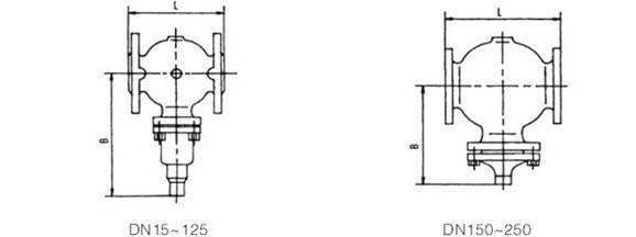
Dimensions and Weights
| Nominal Diameter (mm) | 20 | 25 | 32 | 40 | 50 | 65 | 80 | 100 | 125 | 150 | 200 | 250 |
| L (mm) | 150 | 160 | 180 | 200 | 230 | 290 | 310 | 350 | 400 | 480 | 600 | 730 |
| B (mm) | 212 | 238 | 238 | 240 | 240 | 275 | 275 | 380 | 380 | 295 | 325 | 372 |
| Approximate Weight (kg) | 6.7 | 9.7 | 13 | 14 | 17 | 29 | 33 | 60 | 70 | 80 | 140 | 220 |
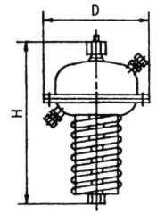
Dimensions and Weights of D02 (D04) Actuators
| Effective Area (cm²) | 32 | 80 | 250 | 630 |
| D (mm) | 172 | 172 | 263 | 380 |
| H (mm) | 435 | 430 | 470 | 520 |
| Approximate Weight (kg) | 7.5 | 7.5 | 13 | 28 |
Dimensions and Weights of D01 (D03) Actuators
| Effective Area (cm²) | 32 | 80 | 250 | 630 |
| D (mm) | 172 | 172 | 263 | 380 |
| H (mm) | 440 | 435 | 440 | 520 |
| Approximate Weight (kg) | 7.5 | 7.5 | 13 | 28 |
Operating Temperature Ranges of Main Component Materials
| Material | Temperature Range (℃) | Remarks |
|---|---|---|
| HT200 | -20 - 200 |
|
| QT400 - 18, QT400 - 15 | -20 - 350 |
|
| ZG230 - 450 | -40 - 450 |
|
| ZG1Cr18Ni9Ti, ZG0Cr18Ni12Mo2Ti | -250 - 550 |
|
| 2Cr13 | -20 - 450 |
|
| 1Cr18Ni9 | -196 - 550 |
|
| 0Cr18Ni12Mo2Ti | -196 - 600 |
|
| Polytetrafluoroethylene | -40 - 200 |
|
| Carbon Fiber | -120 - 350 |
|
| Flexible Graphite | -200 - 600 |
|
| 5860 Glue - Bonded 480D551 Nylon Canvas |
-40 - 80 |
|
(1) Before installation, check that the product model, tag number, and specifications match the requirements. Inspect the entire valve for missing or loose parts.
(2) Prior to installation, clean the pipeline. Ensure there is sufficient straight pipe section at the valve inlet and install a filter. When connecting the valve body to the pipeline flanges, ensure coaxiality.
(3) Thoroughly clean the pipeline before installing the valve.
(4) The installation site should ensure the safety of personnel and equipment, facilitating operation, disassembly, and maintenance.
(5) The valve should be installed vertically upright on horizontal pipelines. If necessary, it can be installed at an angle, but horizontal installation should be avoided. For occasions with heavy valve weight or vibration, use a support frame.
(6) The medium flow direction must align with the arrow on the valve body. The air supply should be dry and oil-free. The valve should be used in environments with temperatures ranging from -20℃ to 55℃.
(1) Cleaning the Valve: For general media, cleaning with water is sufficient. For media harmful to health, first understand their properties and then select an appropriate cleaning method.
(2) Disassembly: Remove rust from exposed rusted parts first. Before derusting, protect the machined surfaces of precision parts such as the valve seat, valve plug, valve stem, and push rod. Use special tools when disassembling the valve seat.
(3) Valve Seat: Minor rust or wear on the sealing surface can be repaired by machining. If damage is severe, replace the seat. However, both repaired and replaced hard sealing surfaces must be lapped.
(4) Valve Stem: If the surface is damaged, it must be replaced.
(5) Damage to Push Rod, Guide, and Sealing Surfaces: Reverse-acting actuators must be replaced; direct-acting actuators can be reused after proper repair.
(6) Compression Spring: If there are cracks or other defects affecting strength, replace it immediately.
(7) Wear Parts: Packing, gaskets, and O-rings must be replaced entirely during each maintenance. Check the valve plug and diaphragm for cracks, aging, or corrosion that may cause future failures. Decide whether to replace them based on inspection results, but the diaphragm service life should not exceed 2-3 years.
(8) When reassembling the valve, ensure alignment. Tighten bolts diagonally and lubricate sliding parts. After reassembly, debug the valve according to the factory test items and methods. During this period, accurately adjust the packing compression force and the valve plug closing position.
-
If the model has not been selected before ordering, please provide us with the operating parameters:
(1) Nominal diameter DN (mm);
(2) Nominal pressure (MPa or bar);
(3) Fluid properties (including medium temperature, viscosity, or acidity/alkalinity);
(4) Pressure before and after the valve (pressure differential);
(5) Requirements for flow characteristics;
(6) Materials of valve body and valve core;
(7) Connection type;
(8) Driving method (provide air supply pressure, driving voltage);
(9) Supporting accessories (for pneumatic valves, it is recommended that users install an air filter triplet and a 2-position 5-way solenoid valve);
(10) On-site working conditions. -
If the product model of our company has been selected by the design unit, please order directly from our production department according to the model;
-
When the application occasion is very important or the pipeline is relatively complex, please provide the design drawings and detailed parameters as much as possible, and our experts will review and check them for you.


