


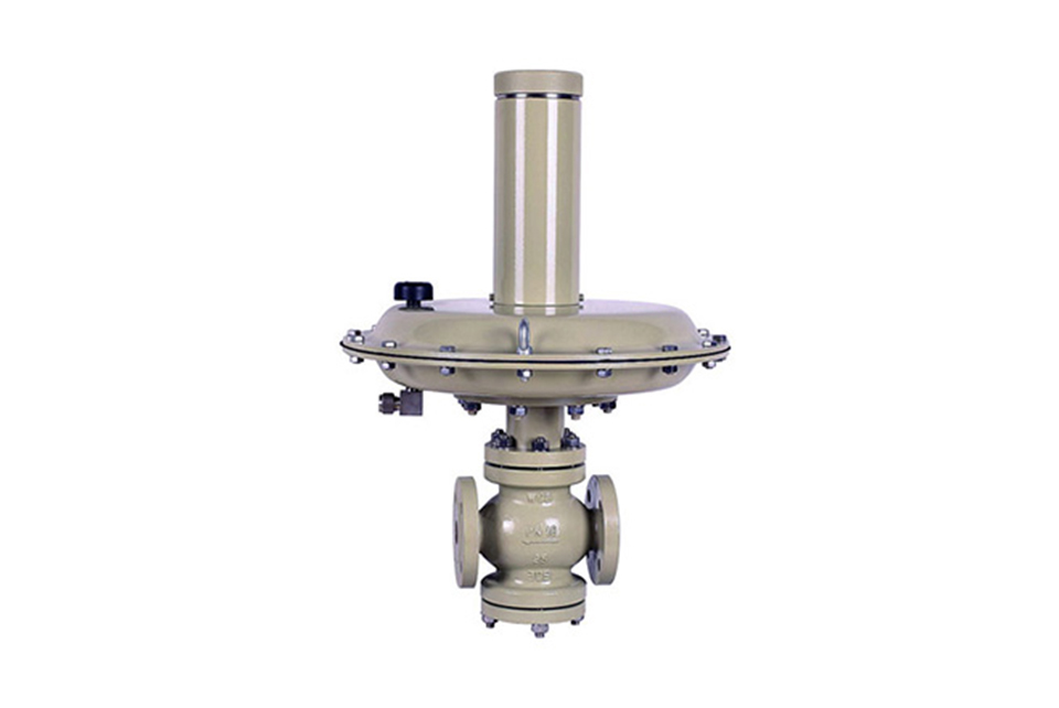
ZZDX nitrogen sealing device - nitrogen release valve
Due to the lack of a specific understanding of the control valve industry in China at present Unified model and naming. The naming of this self regulating valve in the industry is based on the enterprise standards of each company. Example: (Self operated nitrogen supply valve, nitrogen sealing device, nitrogen supply device, self operated pressure regulating valve with commander), etc.
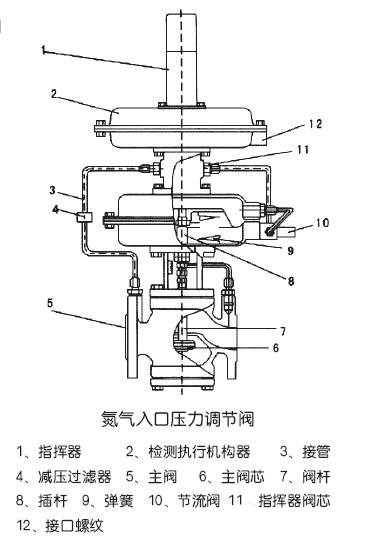
The self operated pressure regulating valve with a controller belongs to the self operated valve series, which uses the pressure of the medium itself to control the valve opening and closing. It adopts a pilot valve structure design, with the pressure behind the valve as the power source, introducing the pressure behind the valve to the controller diaphragm to control the position of the controller valve core, changing the pressure and flow rate of the medium flowing through the controller valve core, and keeping the pressure at the back of the valve precise and constant.
The pressure setting of this valve is achieved by the pressure spring on the controller. After adjusting the compression spring valve, the pressure increases, otherwise it decreases. The operation is simple and therefore convenient, and the accuracy is higher than that of general direct pressure self operated pressure regulating valves; Generally used for nitrogen sealing systems in storage tanks; Adjust and stabilize the nitrogen pressure of the storage tank, with extremely sensitive control accuracy. The control accuracy valve can reach 0.0001MPa (100pa). During operation, the pressure can be continuously adjusted, especially suitable for controlling micro pressure situations.
ZZDX nitrogen sealing device - nitrogen release valve structure
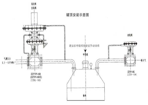
ZZDX nitrogen sealing device - installation diagram of nitrogen release valve
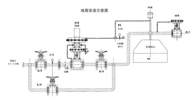
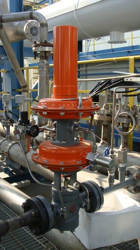
Ground mounted (on-site photo of nitrogen sealing device)
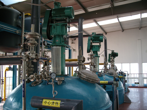
Tank top installation (on-site photo of nitrogen sealing device usage)
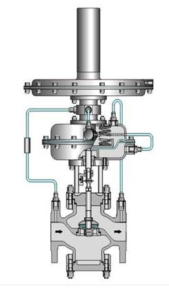
ZZDX nitrogen sealing device - working principle of nitrogen release valve
The nitrogen sealing device consists of a nitrogen supply valve, a nitrogen release valve, and a breathing valve. The nitrogen supply valve consists of a commander and a main valve; The nitrogen release valve is composed of an internally feedback pressure opening type micro pressure regulating valve, and the nitrogen pressure is generally set to 100mmH2O, which is precisely controlled by a nitrogen sealing device. When the inlet valve of the storage tank is opened and materials are added to the tank, the liquid level rises, the volume of the gas phase decreases, and the pressure increases. When the pressure inside the tank rises above the set pressure of the nitrogen release valve, the nitrogen release valve opens and releases nitrogen gas to the outside, causing the pressure inside the tank to decrease. When it reaches the set pressure of the nitrogen release valve, it automatically closes.
When the outlet valve of the storage tank is opened and the user releases the material, the liquid level drops, the volume of the gas phase increases, the pressure inside the tank decreases, and the nitrogen supply valve opens to inject nitrogen into the storage tank, causing the pressure inside the tank to rise and reach the set point of the nitrogen supply valve pressure, which automatically closes.
ZZDX Nitrogen Sealing Device - Material of Nitrogen Release Valve Parts
Part name and material:
Valve body: ZG230-Ni9Ti, ZG1Cr18Ni9Ti, ZG1Cr18Ni12Mo2Ti
Valve core: 1Cr18Ni9Ti, Cr18Ni12Mo2Ti
Diaphragm: Nitrile rubber clip reinforced polyester fabric
| Main Technical Parameters of ZZDX Nitrogen Sealing Device - Nitrogen Relief Valve | ||||||||||||
|---|---|---|---|---|---|---|---|---|---|---|---|---|
| Nominal Diameter DN (mm) | 20 | 25 | 40 | 50 | 80 | 100 | 150 | |||||
| Seat Diameter DN (mm) | 6 | 15 | 20 | 25 | 32 | 40 | 50 | 65 | 80 | 100 | 125 | 150 |
| Rated Flow Coefficient Kv | 3.2 | 5 | 8 | 10 | 20 | 32 | 50 | 80 | 100 | 160 | 250 | 400 |
| Pressure Adjustment Range Kpa | 0.5~70 20~120 60~400 300~700 500~1000 | |||||||||||
| Nominal Pressure PN (Mpa) | 1.0 1.6 | |||||||||||
| Temperature of Medium to be Controlled (℃) | 80 200 | |||||||||||
| Flow Characteristic | Quick Opening | |||||||||||
| Adjustment Accuracy (%) | ≤5 | |||||||||||
| Allowable Pressure Drop (Mpa) | 1.6 | 1.6 | 1.1 | 0.6 | 0.4 | |||||||
| Effective Area of Actuator Diaphragm (C㎡) | 200 | 280 | 400 | |||||||||
| Allowable Leakage | Complies with ANSI B16.104—1976 Class IV | |||||||||||
| Specifications, Weights, and Dimensions of ZZDX Nitrogen Sealing Device - Nitrogen Relief Valve | |||||||
|---|---|---|---|---|---|---|---|
| Nominal Diameter (DN) | 25 | 40 | 50 | 80 | 100 | 150 | |
| Flange End Distance (L) | PN16 | 160 | 200 | 230 | 310 | 350 | 480 |
| A | PN16 | 115 | 150 | 165 | 200 | 220 | 285 |
| B | PN16 | 85 | 110 | 125 | 160 | 180 | 240 |
| H1 | PN16 | 83 | 95 | 110 | 140 | 160 | 230 |
| H2 | PN16 | 325 | |||||
| H | PN16 | 650 | 680 | 750 | 790 | 840 | 990 |
| G | PN16 | 16 | 18 | 20 | 20 | 22 | 24 |
| S | PN16 | 308 | |||||
| nф | PN16 | 4-14 | 4-18 | 4-18 | 4-18 | 4-18 | 8-22 |
| Weight (kg) | 18 | 27 | 40 | 80 | 108 |
262 |
|
(1) Before installation, check that the product model, tag number, and specifications match the requirements. Inspect the entire valve for missing or loose parts.
(2) Prior to installation, clean the pipeline. Ensure there is sufficient straight pipe section at the valve inlet and install a filter. When connecting the valve body to the pipeline flanges, ensure coaxiality.
(3) Thoroughly clean the pipeline before installing the valve.
(4) The installation site should ensure the safety of personnel and equipment, facilitating operation, disassembly, and maintenance.
(5) The valve should be installed vertically upright on horizontal pipelines. If necessary, it can be installed at an angle, but horizontal installation should be avoided. For occasions with heavy valve weight or vibration, use a support frame.
(6) The medium flow direction must align with the arrow on the valve body. The air supply should be dry and oil-free. The valve should be used in environments with temperatures ranging from -20℃ to 55℃.
(1) Cleaning the Valve: For general media, cleaning with water is sufficient. For media harmful to health, first understand their properties and then select an appropriate cleaning method.
(2) Disassembly: Remove rust from exposed rusted parts first. Before derusting, protect the machined surfaces of precision parts such as the valve seat, valve plug, valve stem, and push rod. Use special tools when disassembling the valve seat.
(3) Valve Seat: Minor rust or wear on the sealing surface can be repaired by machining. If damage is severe, replace the seat. However, both repaired and replaced hard sealing surfaces must be lapped.
(4) Valve Stem: If the surface is damaged, it must be replaced.
(5) Damage to Push Rod, Guide, and Sealing Surfaces: Reverse-acting actuators must be replaced; direct-acting actuators can be reused after proper repair.
(6) Compression Spring: If there are cracks or other defects affecting strength, replace it immediately.
(7) Wear Parts: Packing, gaskets, and O-rings must be replaced entirely during each maintenance. Check the valve plug and diaphragm for cracks, aging, or corrosion that may cause future failures. Decide whether to replace them based on inspection results, but the diaphragm service life should not exceed 2-3 years.
(8) When reassembling the valve, ensure alignment. Tighten bolts diagonally and lubricate sliding parts. After reassembly, debug the valve according to the factory test items and methods. During this period, accurately adjust the packing compression force and the valve plug closing position.
-
If the model has not been selected before ordering, please provide us with the operating parameters:
(1) Nominal diameter DN (mm);
(2) Nominal pressure (MPa or bar);
(3) Fluid properties (including medium temperature, viscosity, or acidity/alkalinity);
(4) Pressure before and after the valve (pressure differential);
(5) Requirements for flow characteristics;
(6) Materials of valve body and valve core;
(7) Connection type;
(8) Driving method (provide air supply pressure, driving voltage);
(9) Supporting accessories (for pneumatic valves, it is recommended that users install an air filter triplet and a 2-position 5-way solenoid valve);
(10) On-site working conditions. -
If the product model of our company has been selected by the design unit, please order directly from our production department according to the model;
-
When the application occasion is very important or the pipeline is relatively complex, please provide the design drawings and detailed parameters as much as possible, and our experts will review and check them for you.


