


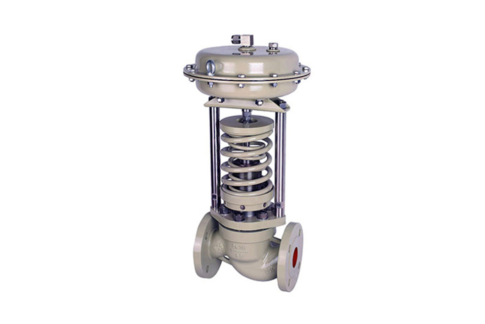
Self operated pressure regulating valve
The series of products includes single seat (ZZYP), sleeve (ZZYM), double seat (ZZYN), and three structures; There are two types of actuators: membrane type and piston type; The types of action include pressure regulation after the pressure reducing valve (Type B) and pressure regulation before the pressure relief valve (Type K). The nominal pressure rating of the product includes PN16, 40, and 64; Valve body diameter range DN20-300; There are three levels of leakage: Level II, Level IV, and Level VI; The traffic characteristic is fast opening; The pressure is adjusted in stages from 15 to 2500Kpa. Can be combined as needed to meet user operating requirements.
Product features of self operated pressure regulating valve
Self operated pressure regulating valves do not require external energy and can work in places without electricity or gas, which is both convenient and energy-saving.
The pressure segmentation range is fine and intersecting with each other, with high adjustment accuracy.
The pressure setting value can be continuously set during operation.
For regulating the pressure after the valve, the ratio of the pressure before the valve to the pressure after the valve can be 10:1-10:8.
Rubber diaphragm type detection, with high precision and sensitive action of the actuator.
Adopting a pressure balance mechanism to make the regulating valve responsive and precise in control.
Material of parts for self operated pressure regulating valve
Valve body: ZG230-450, ZG1Cr18Ni9Ti, ZGCr18Ni12Mo2Ti
Valve core: 1Cr18Ni9Ti, Cr18Ni12Mo2Ti
Valve seat: 1Cr18Ni9Ti, Cr18Ni12Mo2Ti
Valve stem: 1Cr18Ni9Ti, Cr18Ni12Mo2Ti
Membrane cover: A3, A3 steel coated with tetrafluoroethylene stainless steel
Packing: Nitrile, Ethylene Propylene, Fluorine, Oil Resistant Rubber
Connection size and standard of self operated pressure regulating valve
Casting method according to BG9113-88, JB/79-94
Flange sealing surface type: PN16 convex surface
PN40、 64 is concave convex, and the valve body is concave convex
Structure length according to BG12221-98
Execution mechanism signal interface: Internal thread M16 × 1.5
| Specifications and Technical Parameters of Self-Operated Pressure Regulating Valves | ||||||||||||||||||||||||
|---|---|---|---|---|---|---|---|---|---|---|---|---|---|---|---|---|---|---|---|---|---|---|---|---|
| Nominal Diameter DN (mm) | 20 | 25 | 32 | 40 | 50 | 65 | 80 | 100 | 125 | 150 | 200 | 250 | 300 | |||||||||||
| Rated Flow Coefficient (KV) | 7 | 11 | 20 | 30 | 48 | 75 | 120 | 190 | 300 | 480 | 760 | 1100 | 1750 | |||||||||||
| Rated Stroke (mm) | 8 | 10 | 14 | 20 | 25 | 40 | 50 | 60 | 70 | |||||||||||||||
| Nominal Pressure PN (Mpa) | 1.6, 4.0, 6.4 | |||||||||||||||||||||||
| Pressure Regulation Range (MPa) | 15 - 50; 40 - 80; 60 - 100; 80 - 140; 120 - 180; 160 - 220; 200 - 260; 240 - 300; 280 - 350; 330 - 400; 380 - 450; 430 - 500; 480 - 560; 540 - 620; 600 - 700; 680 - 800; 780 - 900; 880 - 1000; 980 - 1500; 1000 - 2500 | |||||||||||||||||||||||
| Flow Characteristic (℃) | Quick Opening | |||||||||||||||||||||||
| Regulation Accuracy (%) | ±5 | |||||||||||||||||||||||
| Operating Temperature (℃) | ≤350 | |||||||||||||||||||||||
| Allowable Leakage | Hard Seal (l/h) | Single Seat: ≤10 - 4 Valve Rated Capacity (Class IV); Double Seat, Sleeve: ≤5 × 10 - 3 Valve Rated Capacity (Class II) | ||||||||||||||||||||||
| Soft Seal (ml/h) | 0.15 | 0.30 | 0.45 | 0.60 | 0.90 | 1.7 | 4.0 | 6.75 | 11.10 | 16.0 | ||||||||||||||
| Pressure Reduction Ratio | Maximum | 10 | ||||||||||||||||||||||
| Minimum | 1.25 | |||||||||||||||||||||||
| Dimensions and Weights of Self-Operated Pressure Regulating Valves | |||||||||||||||
|---|---|---|---|---|---|---|---|---|---|---|---|---|---|---|---|
| Nominal Diameter DN | 20 | 25 | 32 | 40 | 50 | 65 | 80 | 100 | 125 | 150 | 200 | 250 | 300 | ||
| Flange Nozzle Size B | 383 | 512 | 603 | 862 | 1023 | 1380 | 1800 | 2000 | 2200 | ||||||
| Flange End-to-End Distance L | 150 | 160 | 180 | 200 | 230 | 290 | 310 | 350 | 400 | 480 | 600 | 730 | 850 | ||
| Pressure Regulation Range kpa | 15 - 140 | H | 475 | 520 | 540 | 710 | 780 | 840 | 880 | 915 | 940 | 1000 | |||
| A | 280 | 308 |
|
||||||||||||
| 280 - 500 | H | 455 | 500 | 520 | 690 | 760 | 800 | 870 | 880 | 900 | 950 | ||||
| A | 230 | ||||||||||||||
| 120 - 300 | H | 450 | 490 | 510 | 680 | 750 | 790 | 860 | 870 | 890 | 940 | ||||
| A | 176 | 194 | 280 | ||||||||||||
| 480 - 1000 | H | 445 | 480 | 670 | 740 | 780 | 850 | 860 | 880 | 930 | |||||
| A | 176 | 194 | 280 | ||||||||||||
| 600 - 1500 | H | 445 | 570 | 600 | 820 | 890 | 950 | 1000 | 1100 | 1200 | |||||
| A | 85 | 96 | |||||||||||||
| 1000 - 2500 | H | 445 | 570 | 600 | 820 | 890 | 950 | 1000 | 1100 | 1200 |
|
||||
| A | 85 | 96 | |||||||||||||
| Weight kg | 26 | 37 | 42 | 72 | 90 | 114 | 130 | 144 | 180 | 200 | 250 | ||||
| Pressure Tap Thread | M16 × 1.5 | ||||||||||||||
(1) Before installation, check that the product model, tag number, and specifications match the requirements. Inspect the entire valve for missing or loose parts.
(2) Prior to installation, clean the pipeline. Ensure there is sufficient straight pipe section at the valve inlet and install a filter. When connecting the valve body to the pipeline flanges, ensure coaxiality.
(3) Thoroughly clean the pipeline before installing the valve.
(4) The installation site should ensure the safety of personnel and equipment, facilitating operation, disassembly, and maintenance.
(5) The valve should be installed vertically upright on horizontal pipelines. If necessary, it can be installed at an angle, but horizontal installation should be avoided. For occasions with heavy valve weight or vibration, use a support frame.
(6) The medium flow direction must align with the arrow on the valve body. The air supply should be dry and oil-free. The valve should be used in environments with temperatures ranging from -20℃ to 55℃.
(1) Cleaning the Valve: For general media, cleaning with water is sufficient. For media harmful to health, first understand their properties and then select an appropriate cleaning method.
(2) Disassembly: Remove rust from exposed rusted parts first. Before derusting, protect the machined surfaces of precision parts such as the valve seat, valve plug, valve stem, and push rod. Use special tools when disassembling the valve seat.
(3) Valve Seat: Minor rust or wear on the sealing surface can be repaired by machining. If damage is severe, replace the seat. However, both repaired and replaced hard sealing surfaces must be lapped.
(4) Valve Stem: If the surface is damaged, it must be replaced.
(5) Damage to Push Rod, Guide, and Sealing Surfaces: Reverse-acting actuators must be replaced; direct-acting actuators can be reused after proper repair.
(6) Compression Spring: If there are cracks or other defects affecting strength, replace it immediately.
(7) Wear Parts: Packing, gaskets, and O-rings must be replaced entirely during each maintenance. Check the valve plug and diaphragm for cracks, aging, or corrosion that may cause future failures. Decide whether to replace them based on inspection results, but the diaphragm service life should not exceed 2-3 years.
(8) When reassembling the valve, ensure alignment. Tighten bolts diagonally and lubricate sliding parts. After reassembly, debug the valve according to the factory test items and methods. During this period, accurately adjust the packing compression force and the valve plug closing position.
-
If the model has not been selected before ordering, please provide us with the operating parameters:
(1) Nominal diameter DN (mm);
(2) Nominal pressure (MPa or bar);
(3) Fluid properties (including medium temperature, viscosity, or acidity/alkalinity);
(4) Pressure before and after the valve (pressure differential);
(5) Requirements for flow characteristics;
(6) Materials of valve body and valve core;
(7) Connection type;
(8) Driving method (provide air supply pressure, driving voltage);
(9) Supporting accessories (for pneumatic valves, it is recommended that users install an air filter triplet and a 2-position 5-way solenoid valve);
(10) On-site working conditions. -
If the product model of our company has been selected by the design unit, please order directly from our production department according to the model;
-
When the application occasion is very important or the pipeline is relatively complex, please provide the design drawings and detailed parameters as much as possible, and our experts will review and check them for you.


