


Introduction
Performance characteristics
- 1. Excellent micro pressure control performance - The pressure regulator has taken many measures to adapt to precise temperature micro pressure control.
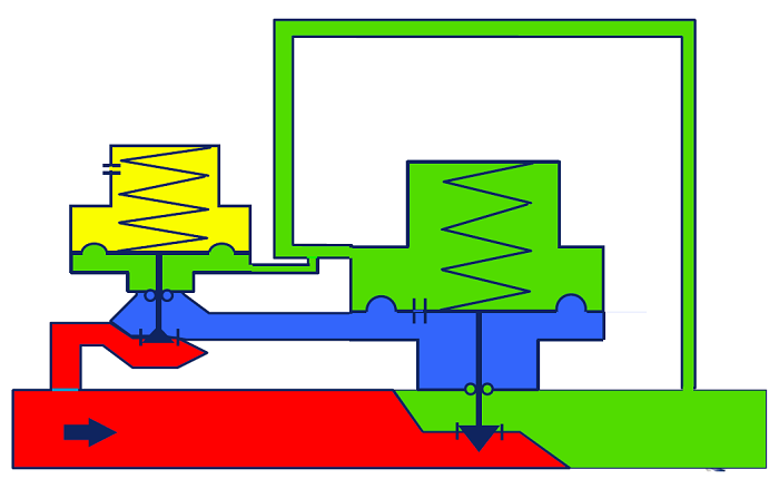
- 2. Leverage amplification - The controller operating mechanism is a lever amplification tension mechanism. Micro pressure control generates extremely small thrust on the diaphragm, and simply increasing the diaphragm area will make the valve volume too large. Through the lever mechanism, the thrust can be amplified by 6 times without increasing the valve volume to meet control needs.
- 3. The control performance of the nozzle type pilot valve - the commander determines the control capability of the entire pressure regulating system. For micro pressure control, any friction and resistance will seriously affect its control effect. The commander valve core adopts a nozzle baffle structure, with no sliding friction and high sensitivity.
- 4. Back pressure control - For pneumatic systems, back pressure control is the most stable. The pressure regulating valve adopts a dual membrane chamber for simultaneous intake, and the back membrane chamber is controlled by a controller nozzle to regulate and release the airflow to achieve stable and precise control.
- 5. Built in pressure reducing valve - The power source of the controller pressure regulating valve comes from the front of the valve, and the pressure in front of the valve is often high and variable. The built-in pressure reducing valve in the commander can reduce the high pressure in front of the valve to a lower and stable air pressure to supply the control system of the pressure regulating valve.
- 6. Safe Overload - In order to minimize the impact of component weight on control pressure, the entire regulating mechanism of the pressure regulating valve is designed according to the principle of being as light, small, and fine as possible. During normal operation, the downstream pressure is extremely low, and the force on the regulating mechanism is very small. However, overload is difficult to avoid in actual use, and downstream pressure may reach the pressure in front of the valve under abnormal conditions. At this time, the thrust generated by the diaphragm component is absolutely destructive to the regulating mechanism. The overload protection mechanism of the pressure regulating valve can effectively unload its overload force, so that the regulating mechanism will not be damaged. That is to say, the actuator diaphragm chamber of the pressure regulating valve can fully withstand the highest operating pressure in front of the valve without damage in most working conditions.
Product Advantages
- 1. The commander is a very precise pneumatic instrument that requires a clean control air source. The pressure regulating valve has a built-in filter on the leading pressure pipe to ensure a clean air source is delivered to the commander.
- 2. The main valve is also driven by a lever, so the pressure regulating valve can be started and regulated normally with a valve front pressure of 15KPa.
- 3. The balanced main valve core enables the pressure regulating valve to have high pressure resistance performance.
- 4. Any frictional resistance during micro pressure control will affect the control accuracy of the pressure regulating valve. The non packing structure of the MN8600 pressure regulating valve provides good sensitivity to the entire regulating mechanism while reducing external leakage points.
- 5. The high-sensitivity commander controls the main valve to achieve high control accuracy of the pressure regulating valve.
- 6. In any control system, it is always desirable for the overshoot to be as small as possible. The MN8600 pressure regulating valve is a one-time throttling valve with a very large pressure reduction ratio, which is prone to overshoot. The commander nozzle is also a quick release valve core. When overpressure occurs, the nozzle valve core will quickly open the two membrane chambers of the balance main valve, causing the main valve to quickly close and minimize the overshoot.
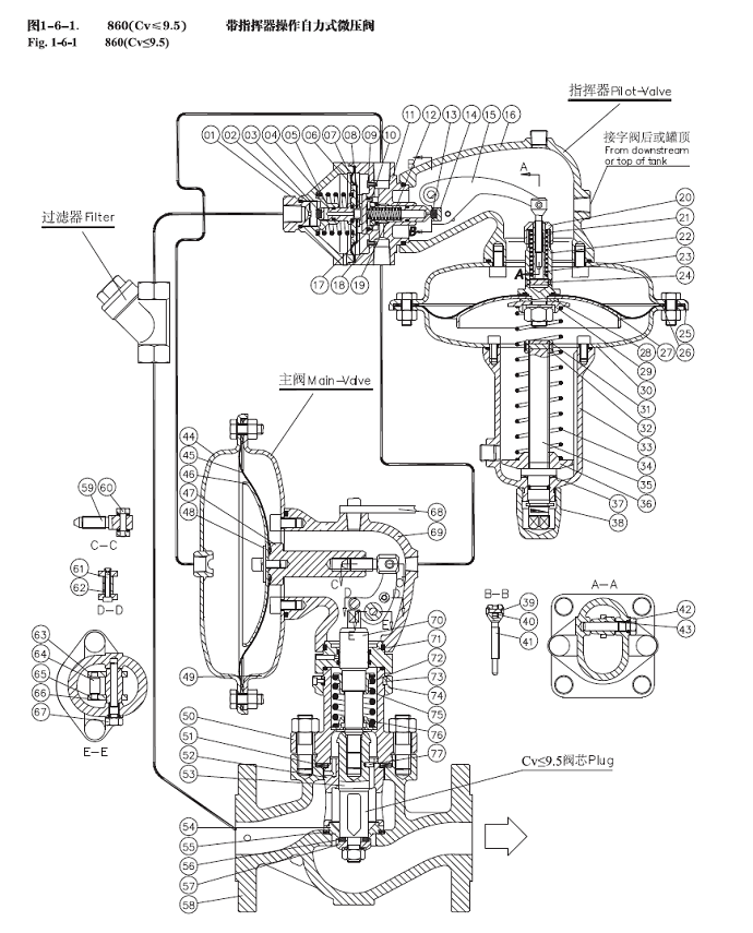
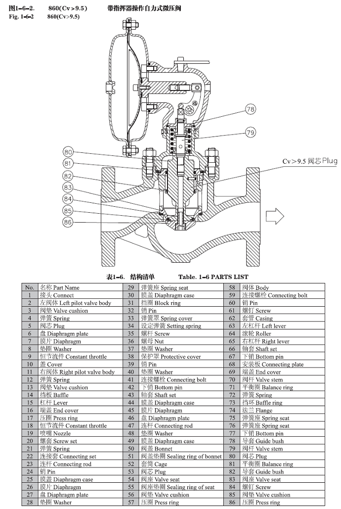
Structural characteristics
Technical Parameter
| Valve Diameter | 1/2"(DN15)~4"(DN100) |
| Nominal Pressure | ANSI Class 150#~600# |
| Operating Temperature | -48~+120℃ |
| Connection Type | Flanged (RF) |
| Body Material | WCB, CF8, CF8M, CF3, CF3M, etc |
| Plug Material | 304(L), 316(L), etc. |
| Leakage Class | ANSI Class IV (Rated Cv × 0.01%) |
| Rangeability | 20:1 |
| Flow Characteristic | Standard Normal |
Valve Installation & Maintenance
Valve Installation:
(1) Before installation, check that the product model, tag number, and specifications match the requirements. Inspect the entire valve for missing or loose parts.
(2) Prior to installation, clean the pipeline. Ensure there is sufficient straight pipe section at the valve inlet and install a filter. When connecting the valve body to the pipeline flanges, ensure coaxiality.
(3) Thoroughly clean the pipeline before installing the valve.
(4) The installation site should ensure the safety of personnel and equipment, facilitating operation, disassembly, and maintenance.
(5) The valve should be installed vertically upright on horizontal pipelines. If necessary, it can be installed at an angle, but horizontal installation should be avoided. For occasions with heavy valve weight or vibration, use a support frame.
(6) The medium flow direction must align with the arrow on the valve body. The air supply should be dry and oil-free. The valve should be used in environments with temperatures ranging from -20℃ to 55℃.
Valve Maintenance:
(1) Cleaning the Valve: For general media, cleaning with water is sufficient. For media harmful to health, first understand their properties and then select an appropriate cleaning method.
(2) Disassembly: Remove rust from exposed rusted parts first. Before derusting, protect the machined surfaces of precision parts such as the valve seat, valve plug, valve stem, and push rod. Use special tools when disassembling the valve seat.
(3) Valve Seat: Minor rust or wear on the sealing surface can be repaired by machining. If damage is severe, replace the seat. However, both repaired and replaced hard sealing surfaces must be lapped.
(4) Valve Stem: If the surface is damaged, it must be replaced.
(5) Damage to Push Rod, Guide, and Sealing Surfaces: Reverse-acting actuators must be replaced; direct-acting actuators can be reused after proper repair.
(6) Compression Spring: If there are cracks or other defects affecting strength, replace it immediately.
(7) Wear Parts: Packing, gaskets, and O-rings must be replaced entirely during each maintenance. Check the valve plug and diaphragm for cracks, aging, or corrosion that may cause future failures. Decide whether to replace them based on inspection results, but the diaphragm service life should not exceed 2-3 years.
(8) When reassembling the valve, ensure alignment. Tighten bolts diagonally and lubricate sliding parts. After reassembly, debug the valve according to the factory test items and methods. During this period, accurately adjust the packing compression force and the valve plug closing position.
Ordering Instructions
When placing an order, please fill in the Specification Sheet or specify the following information:
-
If the model has not been selected before ordering, please provide us with the operating parameters:
(1) Nominal diameter DN (mm);
(2) Nominal pressure (MPa or bar);
(3) Fluid properties (including medium temperature, viscosity, or acidity/alkalinity);
(4) Pressure before and after the valve (pressure differential);
(5) Requirements for flow characteristics;
(6) Materials of valve body and valve core;
(7) Connection type;
(8) Driving method (provide air supply pressure, driving voltage);
(9) Supporting accessories (for pneumatic valves, it is recommended that users install an air filter triplet and a 2-position 5-way solenoid valve);
(10) On-site working conditions. -
If the product model of our company has been selected by the design unit, please order directly from our production department according to the model;
-
When the application occasion is very important or the pipeline is relatively complex, please provide the design drawings and detailed parameters as much as possible, and our experts will review and check them for you.


