


| Product Name |
Masoneilan 21000 Series |
Masoneilan 41005 Series |
Masoneilan 28000 Series |
Masoneilan 80000 Series |
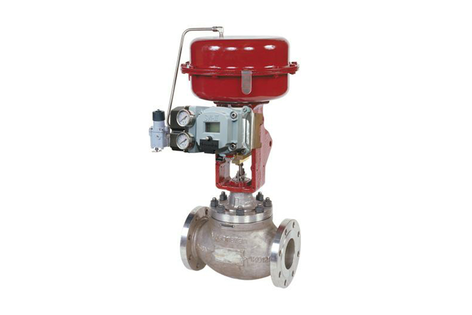
Masoneilan 10000 Series |
|---|---|---|---|---|---|
| Specification |
3/4” to 8” (20 to 200 mm) |
2” to 24” (50 to 600 mm) |
1” (25 mm) Standard 1/2” 3/4” (15 to 20 mm) Available upon request |
1” to 10” (25 to 250 mm) |
2” to 24” (50 to 600 mm) |
| Pressure Class and Connection |
Flange ANSI 150–2500 uni-din 10 - 400; Welding: BW or SW; Thread: NPT 3/4“ to 2” (20 to 50 mm) |
Flange ANSI 150–2500 uni-din 10 - 400; Welding: BW or SW; Thread: NPT 2” (50 mm) |
Flange ANSI 150-600 Between mounting flanges: ANSI 150–2500, uni-din 10- 400; Thread: NPT 1/2“ to 1” (15 to 25 mm) |
Flange ANSI150–600, uni-din 10 - 100; Thread: NPT 3/4“ to 2” (20 to 50 mm); Welding: BW or SW, ANSI 900-2500 upon request |
Flange ANSI150–1500 uni-din 10- 250; Welding: BW or SW; Thread: NPT 3/4“ to 2” (20 to 50 mm) |
| Valve Body Material | Carbon steel; Stainless steel; Chrome-molybdenum alloy steel | Stainless steel; Chrome-molybdenum stainless steel; Monel alloy; |
Stainless steel; Hastelloy alloy steel; 20 alloy steel; |
Stainless steel; Chrome-molybdenum alloy steel; Monel alloy; | Carbon steel; Stainless steel; Chrome-molybdenum steel |
| Actuator | 87/88 Multi-spring diaphragm actuator |
87/88 Multi-spring diaphragm actuator; 37/38 Spring diaphragm actuator; |
Integral spring diaphragm actuator |
87/88 Multi-spring diaphragm actuator; 37/38 Spring diaphragm actuator; |
87/88 Multi-spring diaphragm actuator |
| Valve Plug Material | Single-seat top-guided; Stud and anti-cavitation packing, single-stage or two-stage available. |
Balanced cage type; Lo DB, anti-cavitation and VRT (Variable Resistance Trimming), single-seat and various cage-type valve plugs available |
Complete Stellite needle plug; Various valve plugs available for selection | V-needle | V- or special-shaped needle; Top and bottom guiding |
| Flow Characteristic | Linear or equal percentage | Linear or equal percentage | Linear | Linear | Linear or equal percentage |
| Type | The 21000 series control valve is a heavy-duty top-guided unbalanced design with noise attenuation and anti-cavitation options available. | The 41005 series is a heavy-duty valve design with a balanced configuration. It provides a balanced cage valve seat for increased stability. | The 28000 series varipak * is a compact spherical valve specially designed for microfluidics. It includes an adjustable varipak CV characteristic. | The 80000 series is a three-way control valve for combination or diversion applications. |
The 10000 series is a double-seat valve with top and bottom valve stem guiding, suitable for use with high-pressure differential media under harsh fluid conditions. |
(1) Before installation, check that the product model, tag number, and specifications match the requirements. Inspect the entire valve for missing or loose parts.
(2) Prior to installation, clean the pipeline. Ensure there is sufficient straight pipe section at the valve inlet and install a filter. When connecting the valve body to the pipeline flanges, ensure coaxiality.
(3) Thoroughly clean the pipeline before installing the valve.
(4) The installation site should ensure the safety of personnel and equipment, facilitating operation, disassembly, and maintenance.
(5) The valve should be installed vertically upright on horizontal pipelines. If necessary, it can be installed at an angle, but horizontal installation should be avoided. For occasions with heavy valve weight or vibration, use a support frame.
(6) The medium flow direction must align with the arrow on the valve body. The air supply should be dry and oil-free. The valve should be used in environments with temperatures ranging from -20℃ to 55℃.
(1) Cleaning the Valve: For general media, cleaning with water is sufficient. For media harmful to health, first understand their properties and then select an appropriate cleaning method.
(2) Disassembly: Remove rust from exposed rusted parts first. Before derusting, protect the machined surfaces of precision parts such as the valve seat, valve plug, valve stem, and push rod. Use special tools when disassembling the valve seat.
(3) Valve Seat: Minor rust or wear on the sealing surface can be repaired by machining. If damage is severe, replace the seat. However, both repaired and replaced hard sealing surfaces must be lapped.
(4) Valve Stem: If the surface is damaged, it must be replaced.
(5) Damage to Push Rod, Guide, and Sealing Surfaces: Reverse-acting actuators must be replaced; direct-acting actuators can be reused after proper repair.
(6) Compression Spring: If there are cracks or other defects affecting strength, replace it immediately.
(7) Wear Parts: Packing, gaskets, and O-rings must be replaced entirely during each maintenance. Check the valve plug and diaphragm for cracks, aging, or corrosion that may cause future failures. Decide whether to replace them based on inspection results, but the diaphragm service life should not exceed 2-3 years.
(8) When reassembling the valve, ensure alignment. Tighten bolts diagonally and lubricate sliding parts. After reassembly, debug the valve according to the factory test items and methods. During this period, accurately adjust the packing compression force and the valve plug closing position.
-
If the model has not been selected before ordering, please provide us with the operating parameters:
(1) Nominal diameter DN (mm);
(2) Nominal pressure (MPa or bar);
(3) Fluid properties (including medium temperature, viscosity, or acidity/alkalinity);
(4) Pressure before and after the valve (pressure differential);
(5) Requirements for flow characteristics;
(6) Materials of valve body and valve core;
(7) Connection type;
(8) Driving method (provide air supply pressure, driving voltage);
(9) Supporting accessories (for pneumatic valves, it is recommended that users install an air filter triplet and a 2-position 5-way solenoid valve);
(10) On-site working conditions. -
If the product model of our company has been selected by the design unit, please order directly from our production department according to the model;
-
When the application occasion is very important or the pipeline is relatively complex, please provide the design drawings and detailed parameters as much as possible, and our experts will review and check them for you.


