

A safety valve is a protective valve that prevents the medium pressure in pipelines or equipment from exceeding the specified value by discharging the medium out of the system. As an automatic valve, it is commonly used in boilers, high-pressure vessels, or pipelines to prevent explosion accidents caused by excessive pressure. Safety valves are mainly categorized into pilot-operated and direct-acting types. This article focuses on the basic operation of pilot-operated safety valves.
A pilot-operated safety valve combines a main valve with a self-operated auxiliary safety valve called a pilot valve, where the latter controls the opening and closing of the former. Pilot-operated safety valves can be classified as flow-through or non-flow-through, as well as pop-action or modulating types. For explanations of these pilot types, refer to Figure 1 and Figure 2.
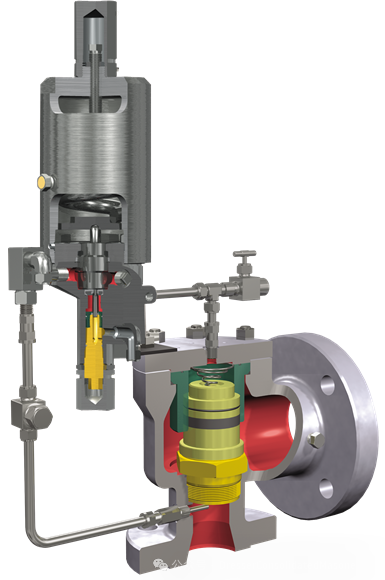
Figure 1: Pop-action pilot safety valve.
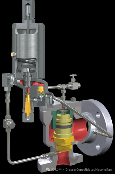
Figure 2: Modulating pilot safety valve.
The pilot valve is driven by the pressure of the pressure-sensing system and uses this pressure to control the closing force of the main valve disc. Increasing system pressure raises the closing force until the pressure drives the pilot valve to open. When the pressure reaches the specified set point, the process medium is discharged through the main valve.
A pop-action pilot configuration causes the main valve disc to "pop" from the closed position to 100% open. When the system returns to normal pressure from an overpressure state, the main valve disc reseats due to medium flowing through the pilot valve to the top of the disc (upper chamber of the main valve).
As shown in Figure 3, system pressure at the main valve inlet is transmitted to the upper chamber of the main valve via interconnected pipelines through the pilot valve. This equalizes the pressure on top of the disc with the inlet pressure at the main valve seat (bottom). Since the area of the disc top is larger than that of the sealing surface, the area difference generates a net downward pressure, keeping the main valve tightly closed.
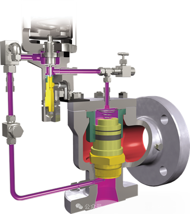
Figure 3: Main valve closed (normal position).
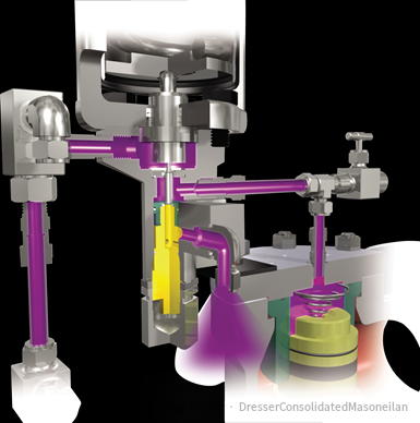
Figure 4: Pilot valve open (relief position).
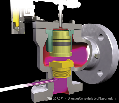
Figure 5: Main valve relieving.
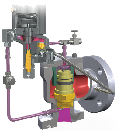
Figure 6: Main valve closed (normal position).
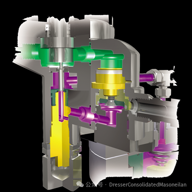
Figure 7: Modulating position.
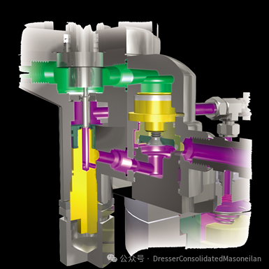
Figure 8: Main valve fully open.
-
Both the main and pilot valves of pilot-operated safety valves can achieve a seal at up to 98% of the set pressure, ensuring zero leakage under normal operating conditions even in demanding high-pressure applications.
-
Compared to spring-loaded valves, pilot-operated valves provide greater seat sealing force, making them ideal for maintaining seals at high operating pressures. Operating near the maximum allowable working pressure (MAWP) helps optimize system performance.
-
Full-bore pilot-operated safety valves deliver higher capacity than standard-ported valves of similar size, allowing customers to reduce costs by using smaller pipelines.
-
During overpressure, modulating pilot-operated valves relieve only the required capacity (not the full rated capacity), enabling users to calculate pipeline losses based on actual system demand rather than rated flow, thereby reducing inlet pipeline pressure loss.
-
On-site test ports allow operators to functionally test the pilot-operated safety valve while it remains installed and protects the system from unexpected overpressure.
-
A dual-pilot option minimizes unplanned shutdowns for maintenance; a backup pilot can be used while the primary one is serviced, allowing scheduled maintenance.
-
The unique design of pilot-operated safety valves connects the pilot to the main valve via interconnected pipelines and supports various accessories, including manual relief valves, filters, check valves, differential pressure switches, pilot lift testers, and remote-mounted pilots.
Like spring-loaded valves, pilot-operated SRVs are widely used across industries, including power generation, refining/petrochemicals, chemicals, oil and gas midstream/upstream, and pulp and paper. Unique applications include high-pressure services, emission reduction in high operating pressure systems, offshore drilling and deep-well wellhead platforms, and services involving air/gas, liquids, steam, two-phase flow, or multi-condition operations.
- News
-
Recommended News
- Basic Operation of Pilot-Operated Safety Relief Valves
- A safety valve is a protective valve that prevents the medium pressure in pipelines or equipment from exceeding the specified value by discharging the medium out of the system. As an automatic valve, it is commonly used in boilers, high-pressure vessels, or pipelines to prevent explosion accidents caused by excessive pressure.
-
Recommended News
- China's Import and Export of Valve Components Increased by 38.24% Year-on-Year
- Statistics on the import and export volume and value of valve parts (for pipelines, boilers, tanks, barrels or similar products) in 2017, as well as the import and export prices and quantities of such parts, show that in March 2017, China's import and export of valve parts increased by 38.24% compared with the same period of the previous year.
-
Recommended News
- Meisonilan to Supply Control Valves for Angola LNG Project
- Angola LNG Project has selected Meisonilan to supply the required control valves. Meisonilan signed the contract with Bechtel's Oil, Gas & Chemicals Global Business Unit, which is responsible for the design, procurement, and construction of the onshore part of the natural gas project.

