2025-06-23Safety Technical Operation Regulations for Safety Valve Adjustment
(1) Adjustment of Opening Pressure
① Before leaving the factory, each safety valve shall be adjusted individually to the set pressure required by the user. If the user specifies a spring working pressure class, the valve shall generally be adjusted to the lower limit of that pressure class before leaving the factory.
② Users must re-adjust the safety valve on-site before installing it on the protected equipment (or during installation) to ensure the set pressure meets the requirements.
③ Within the spring working pressure range indicated on the nameplate, the opening pressure can be adjusted by rotating the adjusting screw to change the spring compression.
④ Before rotating the adjusting screw, reduce the inlet pressure of the valve to below 90% of the opening pressure to prevent the valve disc from rotating with the screw, which may damage the sealing surface.
⑤ To ensure the accuracy of the opening pressure, the medium conditions during adjustment (such as medium type and temperature) should be as close as possible to the actual operating conditions. Changes in the medium type, especially in its aggregation state (e.g., from liquid to gas), often alter the opening pressure. When the operating temperature rises, the opening pressure generally decreases. Therefore, if adjusted at room temperature for high-temperature use, the set pressure at room temperature should be slightly higher than the required opening pressure. The extent of this increase depends on the valve structure and material selection, and shall be based on the manufacturer’s instructions.
⑥ For conventional safety valves used in applications with fixed superimposed backpressure, when adjusting the opening pressure after inspection (with backpressure being atmospheric pressure), the set value shall be the required opening pressure minus the superimposed backpressure.
(2) Adjustment of Discharge Pressure and Blowdown Pressure
① Adjusting the valve’s discharge pressure and blowdown pressure requires a full-opening test. Therefore, this can only be done on large-capacity test equipment or after the safety valve is installed on the protected equipment. The adjustment method varies with the valve structure.
② For valves with a recoil disc and seat adjusting ring, the seat adjusting ring is used for adjustment. Loosen the fixing screws of the adjusting ring, insert a thin iron rod or similar tool into the exposed screw hole, and rotate the adjusting ring via its teeth:
-
Rotating the adjusting ring counterclockwise (left) raises its position, reducing both discharge pressure and blowdown pressure.
-
Rotating it clockwise (right) lowers its position, increasing both pressures.
Each adjustment should involve a small rotation (usually a few teeth). After each adjustment, retighten the fixing screws so that their ends fit into the grooves between the ring’s teeth—this prevents rotation of the adjusting ring without applying radial pressure. For safety, reduce the inlet pressure appropriately (generally below 90% of the opening pressure) before adjusting to avoid sudden valve opening during operation.
③ For structures with upper and lower adjusting rings (one on the guide sleeve and one on the seat), adjustment is more complex:
-
The seat adjusting ring changes the size of the channel between the valve disc and the ring, affecting pressure accumulation in the chamber during initial opening. Raising the seat adjusting ring increases pressure accumulation, reducing the proportional opening phase and accelerating full opening, thereby lowering the discharge pressure. Note: Do not raise the ring too close to the valve disc, as leakage at the sealing surface may cause premature opening followed by immediate closure (chattering), as medium pressure cannot maintain the disc open. The seat adjusting ring primarily reduces the proportional opening phase, adjusts discharge pressure, and slightly affects blowdown pressure.
-
The upper adjusting ring alters the reflection angle of the medium below the valve disc, changing fluid force to adjust blowdown pressure:
-
Raising the upper ring reduces the reflection angle and fluid force, increasing blowdown pressure.
-
Lowering the upper ring increases the reflection angle and fluid force, reducing blowdown pressure.
The upper ring also affects discharge pressure (raising it slightly increases discharge pressure, and lowering it slightly decreases it), but the impact is less significant than on blowdown pressure.
(3) Lead Sealing
After adjustment, the safety valve must be lead-sealed to prevent unauthorized modification of the set parameters. When overhauling the valve, record the positions of the adjusting screw and adjusting ring before disassembly to facilitate re-adjustment. Re-seal with lead after re-adjustment.
2025-06-23Safety Valve Industry Should Find Its Positioning to Explore Domestic and Foreign Markets
With the recovery of the global economy, the import and export of China's safety valve products have increased. However, due to the significant gap in high-end valve technologies compared with foreign manufacturers, product technology will become a bottleneck restricting the development of China's safety valve industry in the coming period.
In response to the above problems and the gap with foreign counterparts in the safety valve industry, China's safety valve sector must reflect carefully to improve existing issues, resolve inconsistencies in development, find the right entry point for development, and jointly promote the revitalization and upgrading of the safety valve industry.
"Aiming at this, it is suggested that safety valve enterprises should turn challenges into opportunities, find their own positioning, focus on exploring domestic and foreign markets (valve market analysis), and mitigate the adverse impact of crises. For Chinese safety valve enterprises, the key is to further improve product quality and technological content. Only by consolidating the foundation and making unremitting efforts in exploration and innovation can China's valve brands gain international recognition," said the person in charge of the Valve Technology Department at Weihai Masoneilan Valve.
As a leading enterprise in the safety valve industry, Weihai Masoneilan Valve has a long-term vision. It is committed to driving industry development through its own growth, promoting industry progress through its own advancement, ultimately achieving a win-win situation for both the enterprise and the industry, and striving to practice the concept of rejuvenating the country through industrial development.
2025-06-23Introduction to Check Valves
Check valves, also known as backflow valves, non-return valves, backpressure valves, or one-way valves, are automatic valves that rely on the force generated by the flow of media in the pipeline to automatically open and close. Used in pipeline systems, their main functions include preventing media backflow, avoiding reverse rotation of pumps and their driving motors, and preventing leakage of media in containers. Additionally, check valves can be installed in pipelines that supply supplementary media to auxiliary systems where pressure may rise above the main system pressure.
Check valves, available in various materials, can be applied to pipelines carrying different media. Once installed in a pipeline, a check valve becomes an integral fluid component of the entire pipeline system. The opening and closing process of its disc is influenced by the transient flow state of the system it is in; conversely, the closing characteristics of the disc also react back on the fluid flow state.
Check valves have distinct working characteristics: they experience large load variations but low opening/closing frequencies. Once in a closed or open state, they can remain functional for extended periods without requiring movement of their components. However, when a "switching" action is needed, the movement must be flexible—a requirement more stringent than that for common mechanical motions.
In most practical applications, check valves are designed for rapid closing. At the moment of closure, the medium flows in the reverse direction, and as the disc closes, the maximum reverse flow velocity drops to zero instantaneously, while pressure rises sharply. This creates a "water hammer" phenomenon that may damage the pipeline system. The water hammer issue is more prominent in high-pressure pipeline systems with multiple parallel pumps. Water hammer is a pressure wave in transient flow within pressure pipelines, caused by the combined effects of fluid incompressibility, fluid inertia, and pipeline elasticity.
To prevent potential water hammer hazards in pipelines, innovations in check valve design—such as new structures and materials—have been developed over the years. These advancements have successfully minimized water hammer impact while ensuring the valve’s performance.
Technical Parameters
-
Nominal Pressure/Pressure Class: PN1.0-16.0MPa, ANSI CLASS 150-900, JIS10-20K
-
Nominal Diameter/Size: DN15~900, NPS 1/4 ~36
-
Connection Methods: Flanged, butt-welded, threaded, socket-welded, etc.
-
Applicable Temperature: -196℃~540℃
-
Valve Body Materials: WCB, ZG1Cr18Ni9Ti, ZG1Cr18Ni12Mo2Ti, CF8 (304), CF3 (304L), CF8M (316), CF3M (316L), Ti.
With different materials, check valves can be used for various media, including water, steam, oil, nitric acid, acetic acid, oxidizing media, urea, and more.
2025-06-23Definition, Function and Classification of Check Valves
Definition of Check Valves
A check valve is a valve that automatically opens and closes its disc relying on the flow of the medium itself, designed to prevent medium backflow. It is also known as a non-return valve, one-way valve, backflow valve, or backpressure valve.
Function of Check Valves
As an automatic valve, the main functions of check valves include: preventing medium backflow, avoiding reverse rotation of pumps and their driving motors, and preventing leakage of medium in containers. Additionally, check valves can be used in pipelines that supply supplementary medium to auxiliary systems where the pressure may rise above the system pressure.
Classification of Check Valves
Check valves can be classified based on their structure and installation method as follows:
1. Swing Check Valves
The disc of a swing check valve is disc-shaped and rotates around a pivot on the valve seat channel. Due to its streamlined internal passage, it has lower flow resistance compared to lift check valves, making it suitable for large-diameter applications with low flow rates and infrequent flow changes. However, it is not ideal for pulsating flow, and its sealing performance is inferior to that of lift check valves.
Swing check valves are divided into three types: single-disc, double-disc, and multi-disc. These types are primarily distinguished by valve diameter, aiming to reduce hydraulic impact when the medium stops flowing or backflows.
2. Lift Check Valves
The disc of a lift check valve slides along the vertical centerline of the valve body. Lift check valves can only be installed on horizontal pipelines. For high-pressure, small-diameter check valves, the disc may be a spherical ball.
The valve body shape of a lift check valve is similar to that of a globe valve (and can be interchangeable with globe valves), resulting in a relatively large flow resistance coefficient. Its structure is similar to a globe valve, with the valve body and disc being identical to those of a globe valve. A guide sleeve is machined on the upper part of the disc and the lower part of the valve cover, allowing the disc to slide freely within the guide sleeve of the valve cover. When the medium flows forward, the disc opens under the medium's thrust; when the medium stops flowing, the disc falls onto the valve seat by its own weight, preventing backflow.
-
Straight-through lift check valves: The direction of the medium inlet/outlet channel is perpendicular to the valve seat channel.
-
Vertical lift check valves: The direction of the medium inlet/outlet channel is the same as the valve seat channel, resulting in lower flow resistance than straight-through types.
3. Disc Check Valves
The disc of a disc check valve rotates around a pin inside the valve seat. It has a simple structure but can only be installed on horizontal pipelines and has poor sealing performance.
4. In-Line Check Valves
The disc of an in-line check valve slides along the centerline of the valve body. As a newly developed valve type, it features small size, light weight, and good manufacturability, representing one of the development directions of check valves. However, its flow resistance coefficient is slightly higher than that of swing check valves.
5. Compact Check Valves
This type of valve is used for boiler feed water and steam shut-off. It combines the functions of a lift check valve with those of a globe valve or angle valve.
2025-06-13Fault Analysis and Handling of Stainless Steel Bellows Globe Valves
Stainless steel bellows globe valves installed in the pipeline of a ship's power plant experienced issues such as stem leakage and stem seizing during operation. Despite repairs, the problems recurred. Through analyzing the causes of the faults and implementing appropriate solutions, the issues were eliminated, ensuring the valve's performance.
Problem Analysis
Leakage in stainless steel bellows globe valves generally falls into two categories: internal leakage and external leakage, with multiple potential causes. Internal leakage is typically due to solid impurities in the liquid medium damaging the sealing surface, leading to failure. Based on on-site usage, the external leakage at the stem is mainly related to the valve structure, working environment, and operational methods:
1. Structure
The valve stem adopts a dual-seal structure combining a bellows and packing. The bellows is welded with an inner liner ring and an outer liner ring to form a bellows assembly, which is then welded to the valve stem and guide body to block medium leakage through the stem. The vertical movement of the valve stem is limited by the upward movement of flat key Ⅰ until the upper end face of flat key Ⅰ contacts the lower end face of the lower packing. Since the lower packing is made of PTFE, excessive opening of the valve will cause flat key Ⅰ to embed into the packing, making the valve inoperable (neither openable nor closable) and potentially damaging the bellows assembly by impact, resulting in medium leakage along the stem.
The stretch length and compression of the bellows are designed according to the valve's stroke. Exceeding the maximum stretch or compression limits may damage the bellows, causing cracks and seal failure. Therefore, it is necessary to add limit devices for valve opening and closing to ensure the bellows expands and contracts within the designed range during operation.
2. Working Environment
The harsh working environment of the bellows globe valve is another contributing factor to faults. Installed inside the ship, the valve operates long-term in a salt spray environment, with condensate often dripping onto its upper part. This causes corrosion of the upper thrust ball bearing, and in severe cases, leads to contact corrosion with the valve stem.
3. Operation
Excessive opening or closing of the bellows globe valve during use may compromise its performance. Over-tightening the valve can damage the sealing surface, resulting in seal failure during subsequent use. Over-opening may damage the bellows assembly, causing external leakage.
Improvements
After analyzing the valve's issues, improvements were made to its structure, operation, and environment:
-
Structural Improvement: A 3mm-thick stainless steel packing gasket was added above the PTFE lower packing to limit the movement of flat key Ⅰ. This prevents the packing from being contaminated and provides a reliable limit for the valve stem.
-
Operational Adjustment:
-
If the valve fails to shut off completely when closing, do not force it closed with excessive force. Instead, open the valve, allow the fluid to flush the sealing surface for a period, then attempt to close it again. Repeat this process if necessary; if it still fails, inspect and grind the sealing surface.
-
When opening the valve, stop applying force once slight resistance is felt at a certain opening height to extend the service life of the valve stem and its sealing components.
-
Environmental Protection: For globe valves with a thrust ball bearing on the upper valve stem, installation should avoid positions where condensate directly drips onto the valve to prevent stem corrosion.
Conclusion
After the improvements, the bellows globe valve no longer experienced faults such as bellows cracks, stem seizing, or external leakage, and has been functioning well.
2025-06-13Introduction to Pneumatic Globe Valves
Pneumatic globe valves are generally fully open and fully closed. From the perspective of flow characteristics, globe valves and ball valves have the characteristics of short opening and closing stroke, fast speed, reliable sealing, and small opening and closing static torque, so both types of products are applied. However, from a reliability perspective, the mainstream product is still the pneumatic globe valve.
The cylinder of the pneumatic globe valve is a standardized product, which can be divided into single acting and double acting according to its mode of action. The single acting product comes with a reset cylindrical spring, which has an automatic reset function when the cylinder piston (or diaphragm) loses air. Under the action of the spring, the cylinder push rod is driven to return to the initial position of the cylinder (the original position of the stroke). The double acting cylinder does not have a reset spring, and the push rod must rely on changing the inlet and outlet positions of the cylinder air source to move forward and backward. When the air source enters the upper chamber of the piston, the push rod moves downward. When the air source enters from the lower chamber of the piston, the push rod moves upward. Due to the absence of a reset spring, double acting cylinders have greater thrust compared to single acting cylinders of the same diameter, but do not have automatic reset function. Obviously, different intake positions cause the push rod to move in different directions. When the intake position is in the back chamber of the push rod, the intake causes the push rod to move forward, which is called a positive action cylinder. On the contrary, when the intake position is on the same side as the push rod, the intake causes the push rod to retract, which is called a reactive cylinder. Pneumatic globe valves usually use single acting cylinders because they require air loss protection function.
2025-06-13Analysis and Handling of Turbine Control Valve Vibration Phenomenon
In a company's Phase I unit, the turbine control valve exhibited opening fluctuations (vibration) when the DEH (Digital Electro-Hydraulic Control System) command remained stable. The main causes of this vibration are analyzed as follows:
(1) The displacement sensor (LVDT) malfunction occurs when the LVDT is installed above the turbine control valve. The high ambient temperature and large vibration can easily cause changes in the resistance value, poor contact, and disconnection of the LVDT coil, resulting in inaccurate position signals from the LVDT. From the working principle of the VCC card controlled by the regulating valve (Figure 1), it can be seen that when the P value is abnormal, even if the A value does not change, the power amplifier part can still receive one driving signal (A-P), and output one current signal (0~± 40mA) to the servo valve to open or close the regulating valve, causing the regulating valve to shake.
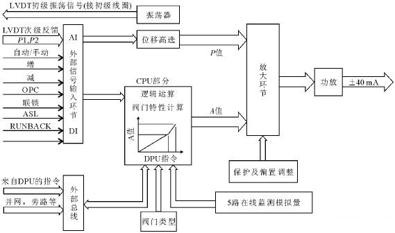
Figure 1: Working principle of VCC card
(2) There are many intermediate links from the DEH to the servo execution part due to line problems, most of which are located near the high-pressure cylinder with high ambient temperature and vibration. The shielding of the cable is easily damaged and interference components are introduced.
(3) Servo valve failure. Servo valve is the core component of the entire DEH system, and its function is to achieve electro-hydraulic conversion. Among them, the magnetic field, coil impedance, and flow state of throttle holes and nozzles have a significant impact on control accuracy and stability. If the magnetic attenuation of the magnet or the impedance change of the coil can affect the deflection angle of the baffle, resulting in a deviation in the oil volume of the inlet and outlet pistons, causing the regulating valve to oscillate repeatedly; If the oil quality of EH is poor, with particles or high viscosity, it can cause blockages and blockages in the throttle holes and nozzles, directly affecting the inlet and outlet oil, causing the regulating valve to react slowly and oscillate, and even get stuck.
The following measures can be taken to address the above issues:
(1) Using two LVDTs, select one of the signals and compare it with the command to ensure that at least one LVDT is in normal condition, in order to avoid fully opening the regulating valve due to a disconnection in either branch coil; Replace the original thick rod LVDT with a thin rod LVDT, and increase the gap between the connecting rod and the LVDT sleeve to avoid twisting or breaking of the connecting rod.
(2) Select high-temperature resistant shielded cables and use dual parallel connections at multiple locations for control signal lines starting from the cabinet to increase system reliability.
(3) When dismantling or installing servo valves, the sealing ring must be replaced every time to avoid interference from strong magnetic fields and air pollution; The storage of spare parts for servo valves must ensure a clean environment and no magnetic field influence.
2020-01-135 Solutions for Abnormal Operation of Control Valves Under High/Low Temperatures
1. Uniform Linear Expansion to Reduce Leakage in Double-Seated Valves
Double-seated valves often show minimal leakage during room-temperature testing but experience a sharp increase in leakage when used at high temperatures. This is due to inconsistent linear expansion between the valve seat sealing surfaces (fixed to the valve body) and the dual sealing surfaces of the valve plug. For example, a DN50 double-seated valve with a stainless steel plug and carbon steel body operating at 70°F will have a 0.06mm expansion difference between the seat and plug sealing surfaces, increasing leakage by over 10 times.
Solutions:
-
Option ①: Use a valve where both the body and plug are made of the same material (e.g., all-stainless steel). However, stainless steel valves cost over 3 times more than carbon steel ones; economic considerations should guide this choice.
-
Option ②: Replace with a sleeve valve, as its sealing surfaces are on the sleeve, and the sleeve and valve plug are made of the same material, eliminating expansion mismatches.
2. Valve Seat Seal Welding
At temperatures up to 750°F, thread-connected valve seats may leak at the sealing interface and threads, risking erosion of threads and even seat detachment. To address this, seal-weld the valve seat to prevent loosening or falling off.
3. Bushing Positioning with Tack Welding
Bushings that guide the valve plug, stem, or disc are mostly interference-fit in normal conditions. During high/low-temperature operation, inconsistent linear expansion can alter fit diameters slightly. In rare cases, minimal interference or foreign object jams may cause the bushing to dislodge when the plug moves. Tack-welding the bushing in position ensures it never detaches.
4. Increasing Bushing Guide Clearance
Under extreme temperatures, if the stem’s linear expansion exceeds that of the bushing’s inner diameter (e.g., in high-temperature butterfly valves), the stem may stick or jump during movement. If the valve’s operating temperature is within its rated range, this may indicate a manufacturing issue. To resolve it:
Enlarge the guide clearance by reducing the stem diameter at the guide section by 0.2–0.5mm, while ensuring a high surface finish.
5. Back-to-Back Packing Installation
For cryogenic valves, vacuum formation in pipelines during cooling can cause external air to leak into the valve through stem packing. Installing part or all of the dual-layer packing in a back-to-back configuration blocks such inward leakage.
2019-06-20Pneumatic Shut-Off Ball Valve
The pneumatic shut-off ball valve consists of a high-precision pneumatic actuator and a high-quality ball valve, belonging to the category of pneumatic on-off ball valves. It features excellent sealing performance, large flow capacity, a simple structure, a long service life, and easy maintenance. The matching actuator is characterized by a simple and compact structure, superior performance, and large output torque.
The pneumatic on-off ball valve can also be equipped with a travel limit switch, solenoid valve, pressure reducing valve, and an air supply of 0.4-0.7MPa to realize on-off operations, and can send out two pairs of passive contact signals to indicate the valve's on-off status. The actuator is available in two models: single-acting and double-acting. A unique advantage of the single-acting type is that in case of a power source failure, the pneumatic on-off ball valve will automatically stay in the open or closed position as required by the control system.
2018-06-13Performance Parameters of Electric Butterfly Valves
Electric butterfly valves are available in two types: on-off type and intelligent type. Equipped with a DSR actuator, the valve can be controlled by inputting a control signal (4~20mADC or 1~5VDC) and a single-phase power supply. It features strong functionality, small size, light weight, low cost, reliable performance, simple matching, and large flow capacity. It is particularly suitable for occasions where the medium is viscous, contains particles, or has fibrous properties. Currently, this valve is widely used in industrial automatic control systems in industries such as food, environmental protection, light industry, petroleum, papermaking, chemical engineering, teaching and research equipment, and electric power.
I. Valve Body (Electric Butterfly Valve Information)
-
Nominal Diameter: 50-1200mm
-
Nominal Pressure: PN1.0, 1.6, 2.5MPa
-
Connection Type: Flanged type (according to JB/T78-59, JB79-59) and wafer-type flange connection
-
Materials: HT200, ZG25I, ZG1Cr18Ni9, ZG0Cr17Ni12Mo2, PTFE-lined metal hard seal
-
Medium Temperature:
-
Normal temperature type: -20°C ~ +200°C
-
Heat dissipation type: -40°C ~ +450°C
II. Valve Trim (Electric Butterfly Valve Information)
-
Spool Form: Valve plate
-
Flow Characteristics: Linear characteristic or equal percentage characteristic
-
Materials: HT200, ZG25I, 1Cr18Ni9Ti, rubber-lined, PTFE-lined
III. Actuator (Electric Butterfly Valve Information)
-
Type: QS series, 3810 series, DSR series electronic angular stroke actuators can be selected.
2017-07-04Working Principle of Pneumatic Ball Valves
The ball of a pneumatic ball valve is evolved from a plug valve. Its ball core rotates 90 degrees, rotating around the center line of the valve body to achieve opening. It has a circular through-hole or channel along its axis. When the ball core rotates 90 degrees, the valve is in a closed state. When the actuator operates, only a small rotational torque is needed to close the valve tightly, thus achieving the principle of rapid shut-off.
Pneumatic ball valves are mainly used in pipelines for rapid shut-off, distribution, and changing the flow direction of media. They open and close quickly and are suitable for both small and large calibers. Using a V-type ball, they can accurately regulate media flow. There are two types of pneumatic ball valve structures:
-
O-type ball core: The O-type ball valve has a floating precision-cast spool, with a flow channel diameter the same as that of the pipeline. It is mainly used as a shut-off switch.
-
V-type ball core: It adopts a fixed structure, with a V-shaped notch on the ball core. After installing a positioner on the actuator, it can realize proportional regulation of media containing fibers or particles.
Introduction to Pneumatic Ball Valves
Pneumatic ball valves are new-type products that replace manual operation by equipping the ball with a pneumatic actuator. The actuator drives the valve body to open and close quickly, achieving shut-off within seconds. They are mainly divided into three types: single-acting, double-acting, and regulating-type. By equipping the pneumatic head with accessories such as a triple unit, positioner, or limit switch, they can be used for throttling and flow regulation. Additionally, with a control box, remote on-off control in the control room can be realized.
Pneumatic ball valves have replaced many traditional manual products, saving significant labor and material resources while enabling simultaneous control of multiple devices and projects. They feature a relatively simple structure, easy maintenance, and high safety. With high-quality materials and proper use, their service life can reach 1 million cycles.
Technical Parameters of Pneumatic Ball Valves
-
Nominal Diameter: DN15-300, 1"-12"
-
Valve Body Pressure: 1.6-10MPa, 150LB-900LB
-
Temperature Range:
-
Soft seal: -20℃-350℃
-
Hard seal: -29℃-580℃
-
Design Standards: GB/T12237-1989, DIN3357/1, 2; API608
-
Flange Dimensions: GB/T9113.1, JB/T79, DIN3202, IS B2002, ASME B16.10
-
Cylinder Type: Double-acting, single-acting (spring-return type)
-
Air Supply Pressure: 4-8bar for double-acting; 5-8bar for single-acting
-
Connection Methods: Threaded, flanged, wafer-type
-
Valve Body Materials: WCB, CF8, CF8M, PVC
-
Seal Materials: PTFE, PPL
-
Medium Range: Water, oil, gas, powder, organic solvents, corrosive liquids, etc.
-
Application Industries: Water treatment, air treatment, metallurgy, natural gas, oil products, chemical industry, papermaking, printing and dyeing, etc.
Optional Actuator Accessories
-
Handwheel mechanism: Enables manual opening/closing of the valve when there is no air pressure.
-
Position feedback device (limit switch): Also called a limit switch, it remotely feeds back switch signals (explosion-proof).
-
Triple unit: Stabilizes air supply pressure, filters, and lubricates the cylinder.
-
Positioner: Inputs 4-20mA signals to realize the regulation function of the ball valve.
-
Solenoid valve: 2-position 5-way for double-acting valves; 2-position 3-way for single-acting valves (explosion-proof).
Classification of Pneumatic Ball Valves
Pneumatic ball valves are mainly classified into: pneumatic floating ball valves, pneumatic fixed ball valves, pneumatic O-type ball valves, pneumatic V-type ball valves, pneumatic eccentric hemispherical valves, pneumatic shut-off valves, pneumatic three-way ball valves, pneumatic four-way ball valves, pneumatic wafer-type ball valves, pneumatic hydraulic ball valves, and pneumatic plastic ball valves.